

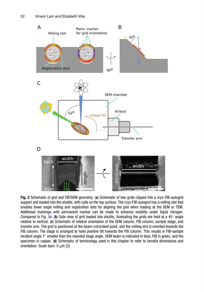
Fig. 2 Schematic of grid and FIB/SEM geometry. (a) Schematic of two grids clipped into a cryo-FIB-autogrid
support and loaded into the shuttle, with cells on the top surface. The cryo-FIB-autogrid has a milling slot that
enables lower angle milling and registration dots for aligning the grid when loading at the SEM or TEM.
Additional markings with permanent marker can be made to enhance visibility under liquid nitrogen.
Compared to Fig. 3e. (b) Side view of grid loaded into shuttle, illustrating the grids are held at a 45
angle
relative to vertical. (c) Schematic of relative orientation of the SEM column, FIB column, sample stage, and
transfer arm. The grid is positioned at the beam-coincident point, and the milling slot is oriented towards the
FIB column. The stage is arranged to have positive tilt towards the FIB column. This results in FIB-sample
incident angle 7
smaller than the reported stage angle. SEM beam is indicated in blue, FIB in green, and the
specimen in copper. (d) Schematic of terminology used in this chapter to refer to lamella dimensions and
orientation. Scale bars: 5 μm [3]
52
Vinson Lam and Elizabeth Villa
support and loaded into the shuttle, with cells on the top surface. The cryo-FIB-autogrid has a milling slot that
enables lower angle milling and registration dots for aligning the grid when loading at the SEM or TEM.
Additional markings with permanent marker can be made to enhance visibility under liquid nitrogen.
Compared to Fig. 3e. (b) Side view of grid loaded into shuttle, illustrating the grids are held at a 45
angle
relative to vertical. (c) Schematic of relative orientation of the SEM column, FIB column, sample stage, and
transfer arm. The grid is positioned at the beam-coincident point, and the milling slot is oriented towards the
FIB column. The stage is arranged to have positive tilt towards the FIB column. This results in FIB-sample
incident angle 7
smaller than the reported stage angle. SEM beam is indicated in blue, FIB in green, and the
specimen in copper. (d) Schematic of terminology used in this chapter to refer to lamella dimensions and
orientation. Scale bars: 5 μm [3]
52
Vinson Lam and Elizabeth Villa