

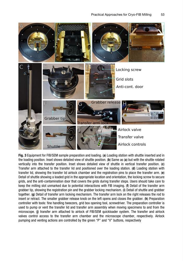
Fig. 3 Equipment for FIB/SEM sample preparation and loading. (a) Loading station with shuttle inserted and in
the loading position. Inset shows detailed view of shuttle position. (b) Same as (a) but with the shuttle rotated
vertically into the transfer position. Inset shows detailed view of shuttle in vertical transfer position. (c)
Transfer arm attached to the transfer lid and positioned over the loading station. (d) Loading station with
transfer lid, showing the transfer lid airlock chamber and the registration pins to place the transfer arm. (e)
Detail of shuttle showing a loaded grid in the appropriate location and orientation, the locking screw to secure
grids, and the anti-contamination door that covers the grids during transfer steps. Users should take care to
keep the milling slot unmarked due to potential interactions with FIB imaging. (f) Detail of the transfer arm
grabber tip, showing the registration pin and the grabber locking mechanism. (i) Detail of shuttle and grabber
together. (g) Detail of transfer arm locking mechanism. The transfer arm lock on the right releases the rod to
insert or retract. The smaller grabber release knob on the left opens and closes the grabber. (h) Preparation
controller with tools: fine handling tweezers, grid box opening tool, screwdriver. The preparation controller is
used to pump or vent the transfer lid and transfer arm assembly when moving specimens to and from the
microscope. (j) transfer arm attached to airlock of FIB/SEM quickloader system. The transfer and airlock
valves control access to the transfer arm chamber and the microscope chamber, respectively. Airlock
pumping and venting actions are controlled by the green “P” and “V” buttons, respectively
Practical Approaches for Cryo-FIB Milling
53
the loading position. Inset shows detailed view of shuttle position. (b) Same as (a) but with the shuttle rotated
vertically into the transfer position. Inset shows detailed view of shuttle in vertical transfer position. (c)
Transfer arm attached to the transfer lid and positioned over the loading station. (d) Loading station with
transfer lid, showing the transfer lid airlock chamber and the registration pins to place the transfer arm. (e)
Detail of shuttle showing a loaded grid in the appropriate location and orientation, the locking screw to secure
grids, and the anti-contamination door that covers the grids during transfer steps. Users should take care to
keep the milling slot unmarked due to potential interactions with FIB imaging. (f) Detail of the transfer arm
grabber tip, showing the registration pin and the grabber locking mechanism. (i) Detail of shuttle and grabber
together. (g) Detail of transfer arm locking mechanism. The transfer arm lock on the right releases the rod to
insert or retract. The smaller grabber release knob on the left opens and closes the grabber. (h) Preparation
controller with tools: fine handling tweezers, grid box opening tool, screwdriver. The preparation controller is
used to pump or vent the transfer lid and transfer arm assembly when moving specimens to and from the
microscope. (j) transfer arm attached to airlock of FIB/SEM quickloader system. The transfer and airlock
valves control access to the transfer arm chamber and the microscope chamber, respectively. Airlock
pumping and venting actions are controlled by the green “P” and “V” buttons, respectively
Practical Approaches for Cryo-FIB Milling
53