

1.1 Principles
of Operation
Cryo-FIB milling is most easily performed using a dual-beam
focused ion beam/scanning electron microscope (FIB/SEM) that
allows simultaneous monitoring and processing of the sample. The
SEM column is mounted vertically onto the chamber and the FIB
column is mounted at a 52
angle relative to the SEM such that the
beams intersect. This intersection point, the beam-coincidence
point, is defined as the working distance of the microscope. In a
well-aligned system, the beam-coincidence point should be located
at the stage eucentric height (Fig. 2).
Samples for cryo-FIB milling are typically prepared on TEM
grids by plunge-freezing (see Subheading 3.1). The grid is positioned at the beam-coincidence point and oriented such that its
surface forms a low incident angle (typically 5
–10
) relative to the
FIB column (Fig. 2c). Milling thus results in lamellae that are nearly
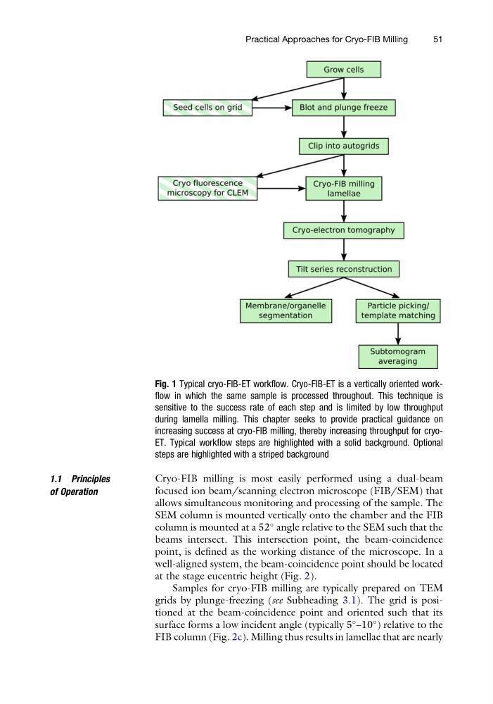
Fig. 1 Typical cryo-FIB-ET workflow. Cryo-FIB-ET is a vertically oriented workflow in which the same sample is processed throughout. This technique is
sensitive to the success rate of each step and is limited by low throughput
during lamella milling. This chapter seeks to provide practical guidance on
increasing success at cryo-FIB milling, thereby increasing throughput for cryoET. Typical workflow steps are highlighted with a solid background. Optional
steps are highlighted with a striped background
Practical Approaches for Cryo-FIB Milling
51
of Operation
Cryo-FIB milling is most easily performed using a dual-beam
focused ion beam/scanning electron microscope (FIB/SEM) that
allows simultaneous monitoring and processing of the sample. The
SEM column is mounted vertically onto the chamber and the FIB
column is mounted at a 52
angle relative to the SEM such that the
beams intersect. This intersection point, the beam-coincidence
point, is defined as the working distance of the microscope. In a
well-aligned system, the beam-coincidence point should be located
at the stage eucentric height (Fig. 2).
Samples for cryo-FIB milling are typically prepared on TEM
grids by plunge-freezing (see Subheading 3.1). The grid is positioned at the beam-coincidence point and oriented such that its
surface forms a low incident angle (typically 5
–10
) relative to the
FIB column (Fig. 2c). Milling thus results in lamellae that are nearly
Fig. 1 Typical cryo-FIB-ET workflow. Cryo-FIB-ET is a vertically oriented workflow in which the same sample is processed throughout. This technique is
sensitive to the success rate of each step and is limited by low throughput
during lamella milling. This chapter seeks to provide practical guidance on
increasing success at cryo-FIB milling, thereby increasing throughput for cryoET. Typical workflow steps are highlighted with a solid background. Optional
steps are highlighted with a striped background
Practical Approaches for Cryo-FIB Milling
51