

magnification and the averaging of these images during generation
of a three-dimensional (3D) reconstruction would degrade the
available high-resolution information.
Three-condenser lens TEMs such as the Thermo Fisher Scientific (formerly FEI) Titan Krios utilize a double zoom condenser
lens system that pairs neighboring lenses (e.g., condenser 1 (C1)—
condenser 2 (C2) and C2—condenser 3 (C3)) with an image plane
between them that can be moved up or down without changing the
position of the image before the first lens or after the second lens
(Fig. 4). Importantly, this configuration maintains a fixed image
distance for the third condenser lens (C3) such that the crossover
below C3 can be maintained in the front focal plane of the objective
lens to produce parallel illumination over a wide range of crossover
positions either between the C1–C2 lenses (i.e., spot size) and the
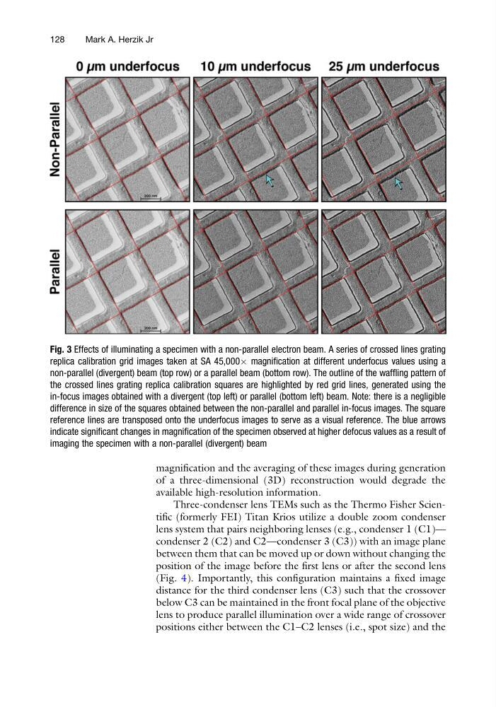
Fig. 3 Effects of illuminating a specimen with a non-parallel electron beam. A series of crossed lines grating
replica calibration grid images taken at SA 45,000Â magnification at different underfocus values using a
non-parallel (divergent) beam (top row) or a parallel beam (bottom row). The outline of the waffling pattern of
the crossed lines grating replica calibration squares are highlighted by red grid lines, generated using the
in-focus images obtained with a divergent (top left) or parallel (bottom left) beam. Note: there is a negligible
difference in size of the squares obtained between the non-parallel and parallel in-focus images. The square
reference lines are transposed onto the underfocus images to serve as a visual reference. The blue arrows
indicate significant changes in magnification of the specimen observed at higher defocus values as a result of
imaging the specimen with a non-parallel (divergent) beam
128
Mark A. Herzik Jr
of a three-dimensional (3D) reconstruction would degrade the
available high-resolution information.
Three-condenser lens TEMs such as the Thermo Fisher Scientific (formerly FEI) Titan Krios utilize a double zoom condenser
lens system that pairs neighboring lenses (e.g., condenser 1 (C1)—
condenser 2 (C2) and C2—condenser 3 (C3)) with an image plane
between them that can be moved up or down without changing the
position of the image before the first lens or after the second lens
(Fig. 4). Importantly, this configuration maintains a fixed image
distance for the third condenser lens (C3) such that the crossover
below C3 can be maintained in the front focal plane of the objective
lens to produce parallel illumination over a wide range of crossover
positions either between the C1–C2 lenses (i.e., spot size) and the
Fig. 3 Effects of illuminating a specimen with a non-parallel electron beam. A series of crossed lines grating
replica calibration grid images taken at SA 45,000Â magnification at different underfocus values using a
non-parallel (divergent) beam (top row) or a parallel beam (bottom row). The outline of the waffling pattern of
the crossed lines grating replica calibration squares are highlighted by red grid lines, generated using the
in-focus images obtained with a divergent (top left) or parallel (bottom left) beam. Note: there is a negligible
difference in size of the squares obtained between the non-parallel and parallel in-focus images. The square
reference lines are transposed onto the underfocus images to serve as a visual reference. The blue arrows
indicate significant changes in magnification of the specimen observed at higher defocus values as a result of
imaging the specimen with a non-parallel (divergent) beam
128
Mark A. Herzik Jr