

frequencies due to differences between the CTF parameters used
for imaging (experimental) and those applied during correction
(estimated), resulting in a considerable loss in resolution. Although
recent advances in data processing algorithms enable refinement of
estimated CTF parameters on a per-particle basis [4–6], these
methodologies are not foolproof, and care should be taken to
illuminate the specimen under ideal conditions rather than to
depend solely on computational correction of aberrations postacquisition. The above example assumes all objects within the
specimen lie on a single plane located at eucentric height within
the objective lens. Due to variations present in nearly all EM specimens, this assumption is almost never satisfied and objects within
the specimen inevitably reside at different Z-heights [7]. If these
objects were imaged using a non-parallel electron beam, then each
object will exhibit a change in magnification that is proportional to:
(a) the distance the object lies away from eucentric height, (b) the
degree by which the electron beam deviates from the parallel conditions (i.e., non-isoplanatism β angle), and (c) the distance the
object lies away from the optical axis. For a tilted specimen, such as
is required for tomography [8] or single particle specimens with
pathologically preferred orientation [9], portions of the image
distant from the optical axis would exhibit a change in magnification that is proportional to: (a) the angle of the specimen tilt,
(b) the degree of deviation from the parallel condition, and
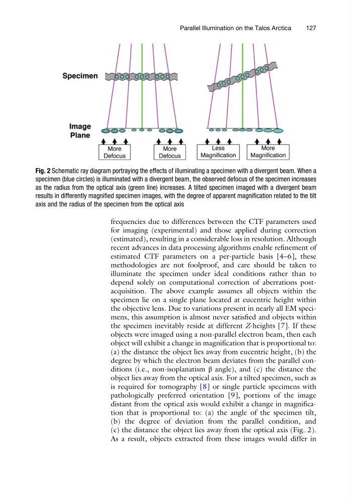
(c) the distance the object lies away from the optical axis (Fig. 2).
As a result, objects extracted from these images would differ in
Fig. 2 Schematic ray diagram portraying the effects of illuminating a specimen with a divergent beam. When a
specimen (blue circles) is illuminated with a divergent beam, the observed defocus of the specimen increases
as the radius from the optical axis (green line) increases. A tilted specimen imaged with a divergent beam
results in differently magnified specimen images, with the degree of apparent magnification related to the tilt
axis and the radius of the specimen from the optical axis
Parallel Illumination on the Talos Arctica
127
for imaging (experimental) and those applied during correction
(estimated), resulting in a considerable loss in resolution. Although
recent advances in data processing algorithms enable refinement of
estimated CTF parameters on a per-particle basis [4–6], these
methodologies are not foolproof, and care should be taken to
illuminate the specimen under ideal conditions rather than to
depend solely on computational correction of aberrations postacquisition. The above example assumes all objects within the
specimen lie on a single plane located at eucentric height within
the objective lens. Due to variations present in nearly all EM specimens, this assumption is almost never satisfied and objects within
the specimen inevitably reside at different Z-heights [7]. If these
objects were imaged using a non-parallel electron beam, then each
object will exhibit a change in magnification that is proportional to:
(a) the distance the object lies away from eucentric height, (b) the
degree by which the electron beam deviates from the parallel conditions (i.e., non-isoplanatism β angle), and (c) the distance the
object lies away from the optical axis. For a tilted specimen, such as
is required for tomography [8] or single particle specimens with
pathologically preferred orientation [9], portions of the image
distant from the optical axis would exhibit a change in magnification that is proportional to: (a) the angle of the specimen tilt,
(b) the degree of deviation from the parallel condition, and
(c) the distance the object lies away from the optical axis (Fig. 2).
As a result, objects extracted from these images would differ in
Fig. 2 Schematic ray diagram portraying the effects of illuminating a specimen with a divergent beam. When a
specimen (blue circles) is illuminated with a divergent beam, the observed defocus of the specimen increases
as the radius from the optical axis (green line) increases. A tilted specimen imaged with a divergent beam
results in differently magnified specimen images, with the degree of apparent magnification related to the tilt
axis and the radius of the specimen from the optical axis
Parallel Illumination on the Talos Arctica
127