

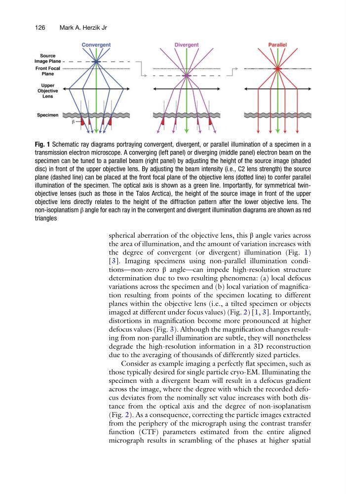
spherical aberration of the objective lens, this β angle varies across
the area of illumination, and the amount of variation increases with
the degree of convergent (or divergent) illumination (Fig. 1)
[3]. Imaging specimens using non-parallel illumination conditions—non-zero β angle—can impede high-resolution structure
determination due to two resulting phenomena: (a) local defocus
variations across the specimen and (b) local variation of magnification resulting from points of the specimen locating to different
planes within the objective lens (i.e., a tilted specimen or objects
imaged at different under focus values) (Fig. 2) [1, 3]. Importantly,
distortions in magnification become more pronounced at higher
defocus values (Fig. 3). Although the magnification changes resulting from non-parallel illumination are subtle, they will nonetheless
degrade the high-resolution information in a 3D reconstruction
due to the averaging of thousands of differently sized particles.
Consider as example imaging a perfectly flat specimen, such as
those typically desired for single particle cryo-EM. Illuminating the
specimen with a divergent beam will result in a defocus gradient
across the image, where the degree with which the recorded defocus deviates from the nominally set value increases with both distance from the optical axis and the degree of non-isoplanatism
(Fig. 2). As a consequence, correcting the particle images extracted
from the periphery of the micrograph using the contrast transfer
function (CTF) parameters estimated from the entire aligned
micrograph results in scrambling of the phases at higher spatial
Fig. 1 Schematic ray diagrams portraying convergent, divergent, or parallel illumination of a specimen in a
transmission electron microscope. A converging (left panel) or diverging (middle panel) electron beam on the
specimen can be tuned to a parallel beam (right panel) by adjusting the height of the source image (shaded
disc) in front of the upper objective lens. By adjusting the beam intensity (i.e., C2 lens strength) the source
plane (dashed line) can be placed at the front focal plane of the objective lens (dotted line) to confer parallel
illumination of the specimen. The optical axis is shown as a green line. Importantly, for symmetrical twinobjective lenses (such as those in the Talos Arctica), the height of the source image in front of the upper
objective lens directly relates to the height of the diffraction pattern after the lower objective lens. The
non-isoplanatism β angle for each ray in the convergent and divergent illumination diagrams are shown as red
triangles
126
Mark A. Herzik Jr
the area of illumination, and the amount of variation increases with
the degree of convergent (or divergent) illumination (Fig. 1)
[3]. Imaging specimens using non-parallel illumination conditions—non-zero β angle—can impede high-resolution structure
determination due to two resulting phenomena: (a) local defocus
variations across the specimen and (b) local variation of magnification resulting from points of the specimen locating to different
planes within the objective lens (i.e., a tilted specimen or objects
imaged at different under focus values) (Fig. 2) [1, 3]. Importantly,
distortions in magnification become more pronounced at higher
defocus values (Fig. 3). Although the magnification changes resulting from non-parallel illumination are subtle, they will nonetheless
degrade the high-resolution information in a 3D reconstruction
due to the averaging of thousands of differently sized particles.
Consider as example imaging a perfectly flat specimen, such as
those typically desired for single particle cryo-EM. Illuminating the
specimen with a divergent beam will result in a defocus gradient
across the image, where the degree with which the recorded defocus deviates from the nominally set value increases with both distance from the optical axis and the degree of non-isoplanatism
(Fig. 2). As a consequence, correcting the particle images extracted
from the periphery of the micrograph using the contrast transfer
function (CTF) parameters estimated from the entire aligned
micrograph results in scrambling of the phases at higher spatial
Fig. 1 Schematic ray diagrams portraying convergent, divergent, or parallel illumination of a specimen in a
transmission electron microscope. A converging (left panel) or diverging (middle panel) electron beam on the
specimen can be tuned to a parallel beam (right panel) by adjusting the height of the source image (shaded
disc) in front of the upper objective lens. By adjusting the beam intensity (i.e., C2 lens strength) the source
plane (dashed line) can be placed at the front focal plane of the objective lens (dotted line) to confer parallel
illumination of the specimen. The optical axis is shown as a green line. Importantly, for symmetrical twinobjective lenses (such as those in the Talos Arctica), the height of the source image in front of the upper
objective lens directly relates to the height of the diffraction pattern after the lower objective lens. The
non-isoplanatism β angle for each ray in the convergent and divergent illumination diagrams are shown as red
triangles
126
Mark A. Herzik Jr