

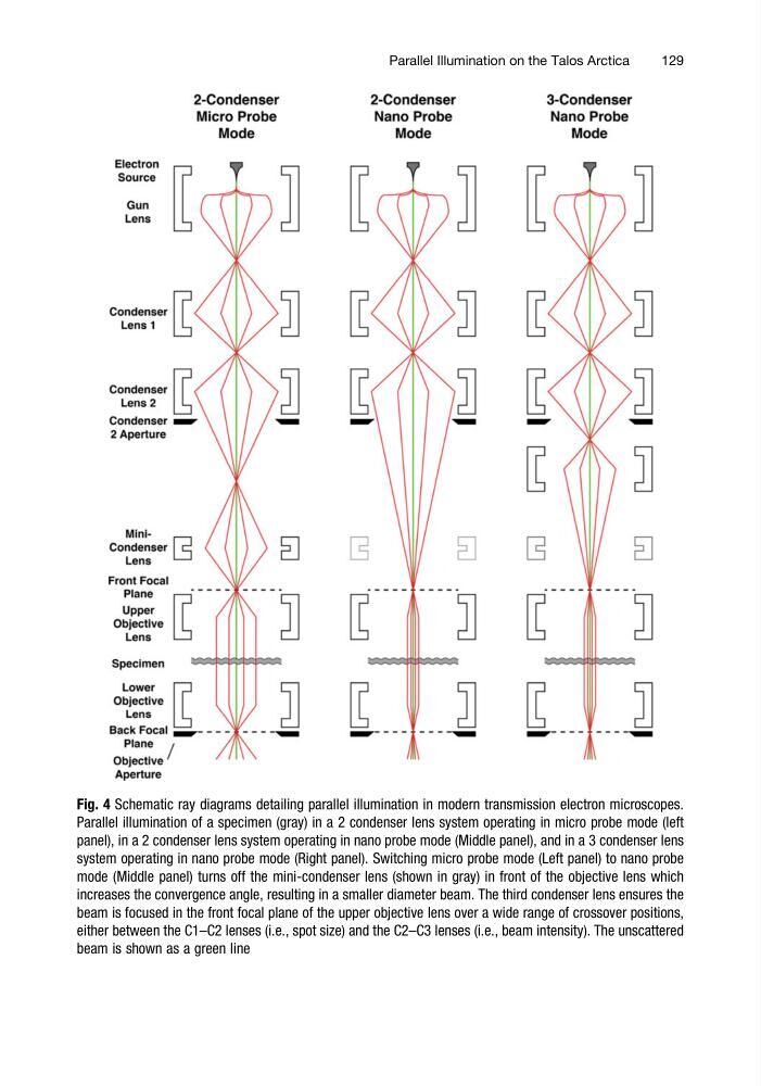
Fig. 4 Schematic ray diagrams detailing parallel illumination in modern transmission electron microscopes.
Parallel illumination of a specimen (gray) in a 2 condenser lens system operating in micro probe mode (left
panel), in a 2 condenser lens system operating in nano probe mode (Middle panel), and in a 3 condenser lens
system operating in nano probe mode (Right panel). Switching micro probe mode (Left panel) to nano probe
mode (Middle panel) turns off the mini-condenser lens (shown in gray) in front of the objective lens which
increases the convergence angle, resulting in a smaller diameter beam. The third condenser lens ensures the
beam is focused in the front focal plane of the upper objective lens over a wide range of crossover positions,
either between the C1–C2 lenses (i.e., spot size) and the C2–C3 lenses (i.e., beam intensity). The unscattered
beam is shown as a green line
Parallel Illumination on the Talos Arctica
129
Parallel illumination of a specimen (gray) in a 2 condenser lens system operating in micro probe mode (left
panel), in a 2 condenser lens system operating in nano probe mode (Middle panel), and in a 3 condenser lens
system operating in nano probe mode (Right panel). Switching micro probe mode (Left panel) to nano probe
mode (Middle panel) turns off the mini-condenser lens (shown in gray) in front of the objective lens which
increases the convergence angle, resulting in a smaller diameter beam. The third condenser lens ensures the
beam is focused in the front focal plane of the upper objective lens over a wide range of crossover positions,
either between the C1–C2 lenses (i.e., spot size) and the C2–C3 lenses (i.e., beam intensity). The unscattered
beam is shown as a green line
Parallel Illumination on the Talos Arctica
129