

J ¼ Uc À D
dc
dx
ð4:1Þ
After reaching a steady-state condition where the two effects U and D cancel out
each other, the net flux J ¼ 0 and
Uc ¼ D
dc
dx
ð4:2Þ
By means of integration and substituting the boundary values, a concentration
profile is obtained with
c x
ð Þ ¼ c 0 e
À U
j j
D
ð Þx
ð4:3Þ
where c 0 is the solute concentration at the accumulation wall, U is the applied force
velocity and D the diffusion coefficient of the solute. As a result of the concentration gradient, the concentration decreases exponentially as the solute molecules
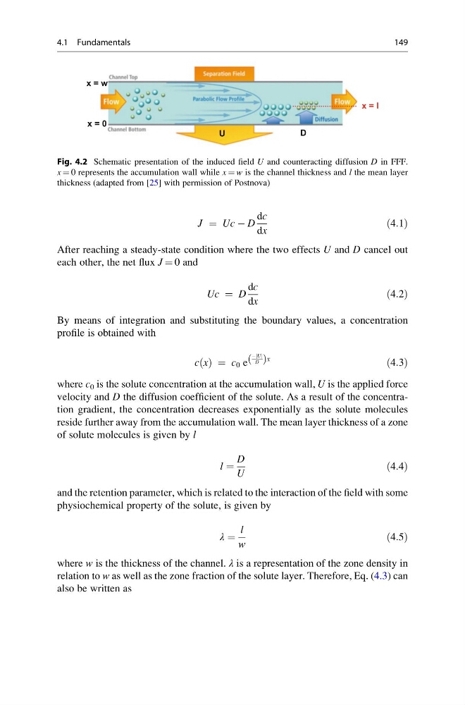
reside further away from the accumulation wall. The mean layer thickness of a zone
of solute molecules is given by l
l ¼
D
U
ð4:4Þ
and the retention parameter, which is related to the interaction of the field with some
physiochemical property of the solute, is given by
λ ¼
l
w
ð4:5Þ
where w is the thickness of the channel. λ is a representation of the zone density in
relation to w as well as the zone fraction of the solute layer. Therefore, Eq. (4.3) can
also be written as
U
D
x = 0
x = w
x = l
Fig. 4.2 Schematic presentation of the induced field U and counteracting diffusion D in FFF.
x ¼ 0 represents the accumulation wall while x ¼ w is the channel thickness and l the mean layer
thickness (adapted from [25] with permission of Postnova)
4.1 Fundamentals
149
dc
dx
ð4:1Þ
After reaching a steady-state condition where the two effects U and D cancel out
each other, the net flux J ¼ 0 and
Uc ¼ D
dc
dx
ð4:2Þ
By means of integration and substituting the boundary values, a concentration
profile is obtained with
c x
ð Þ ¼ c 0 e
À U
j j
D
ð Þx
ð4:3Þ
where c 0 is the solute concentration at the accumulation wall, U is the applied force
velocity and D the diffusion coefficient of the solute. As a result of the concentration gradient, the concentration decreases exponentially as the solute molecules
reside further away from the accumulation wall. The mean layer thickness of a zone
of solute molecules is given by l
l ¼
D
U
ð4:4Þ
and the retention parameter, which is related to the interaction of the field with some
physiochemical property of the solute, is given by
λ ¼
l
w
ð4:5Þ
where w is the thickness of the channel. λ is a representation of the zone density in
relation to w as well as the zone fraction of the solute layer. Therefore, Eq. (4.3) can
also be written as
U
D
x = 0
x = w
x = l
Fig. 4.2 Schematic presentation of the induced field U and counteracting diffusion D in FFF.
x ¼ 0 represents the accumulation wall while x ¼ w is the channel thickness and l the mean layer
thickness (adapted from [25] with permission of Postnova)
4.1 Fundamentals
149