

4 Reflective Arterial Pulse Oximetry for New Measuring Sites …
83
Fig. 4.2 Monitoring device for standard application behind the auricle: with a flexible band for
sensor connection (at the top) and a micro USB charging port (below)
can be worn behind the auricle. The measurement device drives the bidirectional
LEDs and converts the photocurrent into digital values. The digitized rPPG signals
are preprocessed by a microcontroller and sent via Bluetooth to a computational
interface device (i.e., PC, tablet, smartphone, etc.). The communication is based
on the energy-efficient Bluetooth 4.0 standard, making the system compatible with
widely-used communication devices.
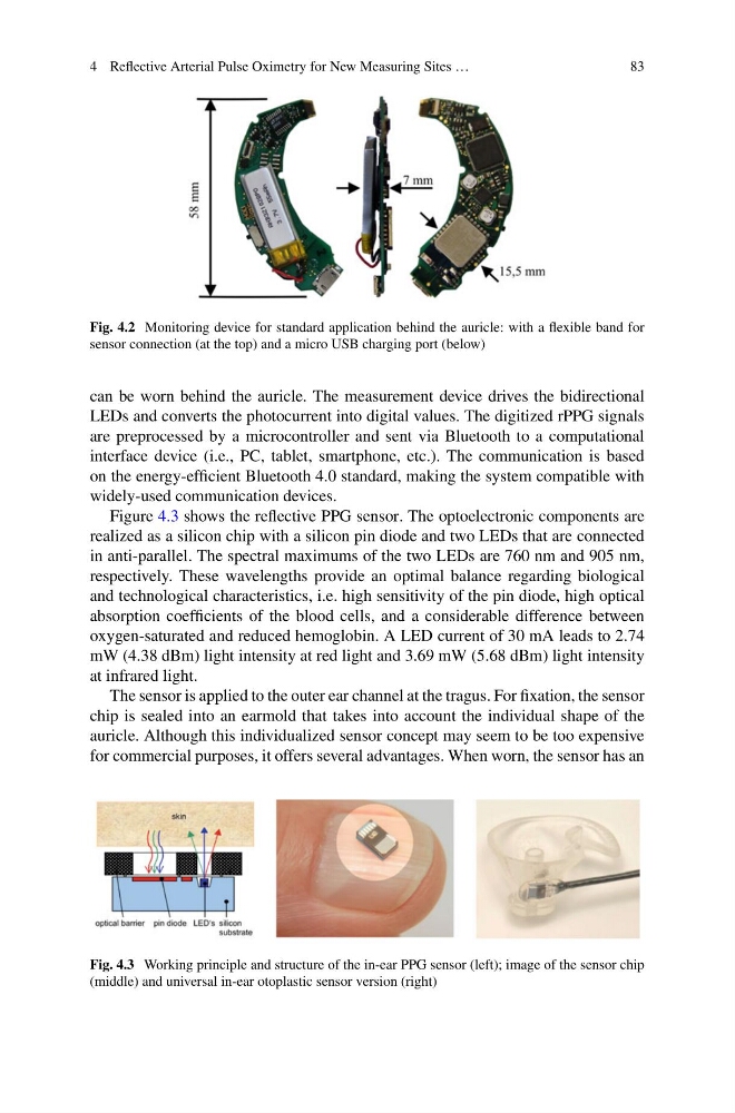
Figure 4.3 shows the reflective PPG sensor. The optoelectronic components are
realized as a silicon chip with a silicon pin diode and two LEDs that are connected
in anti-parallel. The spectral maximums of the two LEDs are 760 nm and 905 nm,
respectively. These wavelengths provide an optimal balance regarding biological
and technological characteristics, i.e. high sensitivity of the pin diode, high optical
absorption coefficients of the blood cells, and a considerable difference between
oxygen-saturated and reduced hemoglobin. A LED current of 30 mA leads to 2.74
mW (4.38 dBm) light intensity at red light and 3.69 mW (5.68 dBm) light intensity
at infrared light.
The sensor is applied to the outer ear channel at the tragus. For fixation, the sensor
chip is sealed into an earmold that takes into account the individual shape of the
auricle. Although this individualized sensor concept may seem to be too expensive
for commercial purposes, it offers several advantages. When worn, the sensor has an
Fig. 4.3 Working principle and structure of the in-ear PPG sensor (left); image of the sensor chip
(middle) and universal in-ear otoplastic sensor version (right)
83
Fig. 4.2 Monitoring device for standard application behind the auricle: with a flexible band for
sensor connection (at the top) and a micro USB charging port (below)
can be worn behind the auricle. The measurement device drives the bidirectional
LEDs and converts the photocurrent into digital values. The digitized rPPG signals
are preprocessed by a microcontroller and sent via Bluetooth to a computational
interface device (i.e., PC, tablet, smartphone, etc.). The communication is based
on the energy-efficient Bluetooth 4.0 standard, making the system compatible with
widely-used communication devices.
Figure 4.3 shows the reflective PPG sensor. The optoelectronic components are
realized as a silicon chip with a silicon pin diode and two LEDs that are connected
in anti-parallel. The spectral maximums of the two LEDs are 760 nm and 905 nm,
respectively. These wavelengths provide an optimal balance regarding biological
and technological characteristics, i.e. high sensitivity of the pin diode, high optical
absorption coefficients of the blood cells, and a considerable difference between
oxygen-saturated and reduced hemoglobin. A LED current of 30 mA leads to 2.74
mW (4.38 dBm) light intensity at red light and 3.69 mW (5.68 dBm) light intensity
at infrared light.
The sensor is applied to the outer ear channel at the tragus. For fixation, the sensor
chip is sealed into an earmold that takes into account the individual shape of the
auricle. Although this individualized sensor concept may seem to be too expensive
for commercial purposes, it offers several advantages. When worn, the sensor has an
Fig. 4.3 Working principle and structure of the in-ear PPG sensor (left); image of the sensor chip
(middle) and universal in-ear otoplastic sensor version (right)