

The geometrical constraints imposed by the ZL host determine the organization
of the dyes. This allows for sequential insertion of different guests, resulting in
organized pattern, as we have illustrated in Fig. 26. Applying this principle soon led
to the first artificial photonic antenna composite consisting of three different dyes:
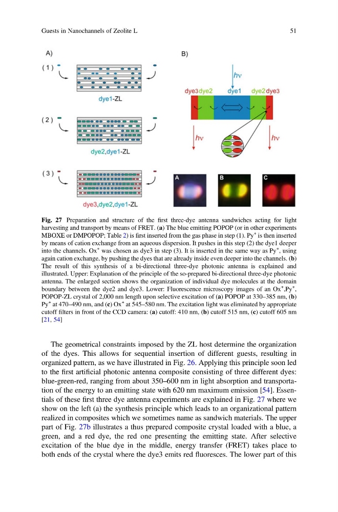
blue-green-red, ranging from about 350–600 nm in light absorption and transportation of the energy to an emitting state with 620 nm maximum emission [54]. Essentials of these first three dye antenna experiments are explained in Fig. 27 where we
show on the left (a) the synthesis principle which leads to an organizational pattern
realized in composites which we sometimes name as sandwich materials. The upper
part of Fig. 27b illustrates a thus prepared composite crystal loaded with a blue, a
green, and a red dye, the red one presenting the emitting state. After selective
excitation of the blue dye in the middle, energy transfer (FRET) takes place to
both ends of the crystal where the dye3 emits red fluoresces. The lower part of this
Fig. 27 Preparation and structure of the first three-dye antenna sandwiches acting for light
harvesting and transport by means of FRET. (a) The blue emitting POPOP (or in other experiments
MBOXE or DMPOPOP; Table 2) is first inserted from the gas phase in step (1). Py
+ is then inserted
by means of cation exchange from an aqueous dispersion. It pushes in this step (2) the dye1 deeper
into the channels. Ox
+ was chosen as dye3 in step (3). It is inserted in the same way as Py
+ , using
again cation exchange, by pushing the dyes that are already inside even deeper into the channels. (b)
The result of this synthesis of a bi-directional three-dye photonic antenna is explained and
illustrated. Upper: Explanation of the principle of the so-prepared bi-directional three-dye photonic
antenna. The enlarged section shows the organization of individual dye molecules at the domain
boundary between the dye2 and dye3. Lower: Fluorescence microscopy images of an Ox
+ ,Py
+ ,
POPOP-ZL crystal of 2,000 nm length upon selective excitation of (a) POPOP at 330–385 nm, (b)
Py
+ at 470–490 nm, and (c) Ox
+ at 545–580 nm. The excitation light was eliminated by appropriate
cutoff filters in front of the CCD camera: (a) cutoff: 410 nm, (b) cutoff 515 nm, (c) cutoff 605 nm
[21, 54]
Guests in Nanochannels of Zeolite L
51
of the dyes. This allows for sequential insertion of different guests, resulting in
organized pattern, as we have illustrated in Fig. 26. Applying this principle soon led
to the first artificial photonic antenna composite consisting of three different dyes:
blue-green-red, ranging from about 350–600 nm in light absorption and transportation of the energy to an emitting state with 620 nm maximum emission [54]. Essentials of these first three dye antenna experiments are explained in Fig. 27 where we
show on the left (a) the synthesis principle which leads to an organizational pattern
realized in composites which we sometimes name as sandwich materials. The upper
part of Fig. 27b illustrates a thus prepared composite crystal loaded with a blue, a
green, and a red dye, the red one presenting the emitting state. After selective
excitation of the blue dye in the middle, energy transfer (FRET) takes place to
both ends of the crystal where the dye3 emits red fluoresces. The lower part of this
Fig. 27 Preparation and structure of the first three-dye antenna sandwiches acting for light
harvesting and transport by means of FRET. (a) The blue emitting POPOP (or in other experiments
MBOXE or DMPOPOP; Table 2) is first inserted from the gas phase in step (1). Py
+ is then inserted
by means of cation exchange from an aqueous dispersion. It pushes in this step (2) the dye1 deeper
into the channels. Ox
+ was chosen as dye3 in step (3). It is inserted in the same way as Py
+ , using
again cation exchange, by pushing the dyes that are already inside even deeper into the channels. (b)
The result of this synthesis of a bi-directional three-dye photonic antenna is explained and
illustrated. Upper: Explanation of the principle of the so-prepared bi-directional three-dye photonic
antenna. The enlarged section shows the organization of individual dye molecules at the domain
boundary between the dye2 and dye3. Lower: Fluorescence microscopy images of an Ox
+ ,Py
+ ,
POPOP-ZL crystal of 2,000 nm length upon selective excitation of (a) POPOP at 330–385 nm, (b)
Py
+ at 470–490 nm, and (c) Ox
+ at 545–580 nm. The excitation light was eliminated by appropriate
cutoff filters in front of the CCD camera: (a) cutoff: 410 nm, (b) cutoff 515 nm, (c) cutoff 605 nm
[21, 54]
Guests in Nanochannels of Zeolite L
51