

dyes Py
+ and Ox
+
, used as example donor-acceptor pair in this study, was not known
at this time and was later found to be more complex than assumed. Fluorescence
microscopy combined with single-crystal imaging [149], two-photon fluorescence
polarimetric microscopy [165], and extensive first-principles investigations led to
the result that different preferential orientations must be considered in the presence
or absence of water because of the dominant stabilization of either the host or the
guest, respectively. Optical microscopy data might therefore be reinterpreted as the
vector sum of components arising from a population of molecules with non-uniform
orientation [153]. This understanding does not affect the essentials of the procedure
and the derived consequences reported in [151], but they affect some details of the
numerical outcome. Py
+ and Ox
+ are very nice donor-acceptor pair for demonstrating many aspects of FRET resulting from their organization inside of the ZL
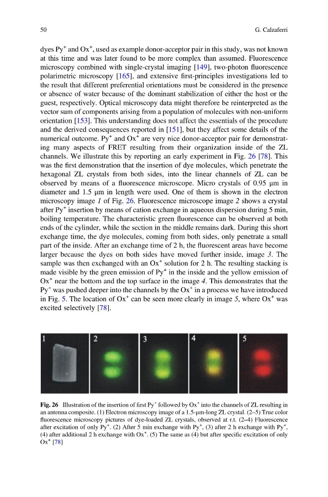
channels. We illustrate this by reporting an early experiment in Fig. 26 [78]. This
was the first demonstration that the insertion of dye molecules, which penetrate the
hexagonal ZL crystals from both sides, into the linear channels of ZL can be
observed by means of a fluorescence microscope. Micro crystals of 0.95 μm in
diameter and 1.5 μm in length were used. One of them is shown in the electron
microscopy image 1 of Fig. 26. Fluorescence microscope image 2 shows a crystal
after Py
+ insertion by means of cation exchange in aqueous dispersion during 5 min,
boiling temperature. The characteristic green fluorescence can be observed at both
ends of the cylinder, while the section in the middle remains dark. During this short
exchange time, the dye molecules, coming from both sides, only penetrate a small
part of the inside. After an exchange time of 2 h, the fluorescent areas have become
larger because the dyes on both sides have moved further inside, image 3. The
sample was then exchanged with an Ox
+ solution for 2 h. The resulting stacking is
made visible by the green emission of Py
+ in the inside and the yellow emission of
Ox
+ near the bottom and the top surface in the image 4. This demonstrates that the
Py
+ was pushed deeper into the channels by the Ox
+ in a process we have introduced
in Fig. 5. The location of Ox
+ can be seen more clearly in image 5, where Ox
+ was
excited selectively [78].
Fig. 26 Illustration of the insertion of first Py
+ followed by Ox
+ into the channels of ZL resulting in
an antenna composite. (1) Electron microscopy image of a 1.5-μm-long ZL crystal. (2–5) True color
fluorescence microscopy pictures of dye-loaded ZL crystals, observed at r.t. (2–4) Fluorescence
after excitation of only Py
+ . (2) After 5 min exchange with Py
+ , (3) after 2 h exchange with Py
+ ,
(4) after additional 2 h exchange with Ox
+ . (5) The same as (4) but after specific excitation of only
Ox
+ [78]
50
G. Calzaferri
+ and Ox
+
, used as example donor-acceptor pair in this study, was not known
at this time and was later found to be more complex than assumed. Fluorescence
microscopy combined with single-crystal imaging [149], two-photon fluorescence
polarimetric microscopy [165], and extensive first-principles investigations led to
the result that different preferential orientations must be considered in the presence
or absence of water because of the dominant stabilization of either the host or the
guest, respectively. Optical microscopy data might therefore be reinterpreted as the
vector sum of components arising from a population of molecules with non-uniform
orientation [153]. This understanding does not affect the essentials of the procedure
and the derived consequences reported in [151], but they affect some details of the
numerical outcome. Py
+ and Ox
+ are very nice donor-acceptor pair for demonstrating many aspects of FRET resulting from their organization inside of the ZL
channels. We illustrate this by reporting an early experiment in Fig. 26 [78]. This
was the first demonstration that the insertion of dye molecules, which penetrate the
hexagonal ZL crystals from both sides, into the linear channels of ZL can be
observed by means of a fluorescence microscope. Micro crystals of 0.95 μm in
diameter and 1.5 μm in length were used. One of them is shown in the electron
microscopy image 1 of Fig. 26. Fluorescence microscope image 2 shows a crystal
after Py
+ insertion by means of cation exchange in aqueous dispersion during 5 min,
boiling temperature. The characteristic green fluorescence can be observed at both
ends of the cylinder, while the section in the middle remains dark. During this short
exchange time, the dye molecules, coming from both sides, only penetrate a small
part of the inside. After an exchange time of 2 h, the fluorescent areas have become
larger because the dyes on both sides have moved further inside, image 3. The
sample was then exchanged with an Ox
+ solution for 2 h. The resulting stacking is
made visible by the green emission of Py
+ in the inside and the yellow emission of
Ox
+ near the bottom and the top surface in the image 4. This demonstrates that the
Py
+ was pushed deeper into the channels by the Ox
+ in a process we have introduced
in Fig. 5. The location of Ox
+ can be seen more clearly in image 5, where Ox
+ was
excited selectively [78].
Fig. 26 Illustration of the insertion of first Py
+ followed by Ox
+ into the channels of ZL resulting in
an antenna composite. (1) Electron microscopy image of a 1.5-μm-long ZL crystal. (2–5) True color
fluorescence microscopy pictures of dye-loaded ZL crystals, observed at r.t. (2–4) Fluorescence
after excitation of only Py
+ . (2) After 5 min exchange with Py
+ , (3) after 2 h exchange with Py
+ ,
(4) after additional 2 h exchange with Ox
+ . (5) The same as (4) but after specific excitation of only
Ox
+ [78]
50
G. Calzaferri