

figure shows fluorescence microscopy images of such a photonic antenna. We
observe that after selective excitation of dye1 (POPOP), located in the middle part,
the light energy is carried spectrally from the blue to green (dye2, Py
+
) to red (dye3,
Ox
+
) and spatially from the crystal center to its both ends. The stacking of the dyes in
the crystal can be seen in microscopy images taken on an approximately 2,000-nmlong crystal. Image A shows the fluorescence observed after selective excitation of
the POPOP and applying a 410 nm cutoff filter in front of the monitoring CCD
camera. The middle of the crystal shows the blue fluorescence of POPOP, while the
red emission of Ox
+ appears at both ends. Between these two zones, the superposition of the fluorescence of all three dyes results in emission of white light. The
fluorescence, after selective excitation of the Py
+ and applying a 515 nm cutoff filter,
is seen in image B. The yellow emission is due to superposition of the green Py
+ and
the red Ox
+
fluorescence. Image c, finally, shows the emission of Ox
+ after selective
excitation of only Ox
+ and applying a 605 nm cutoff filter. These three microscopy
images show very nicely the sequence of the inserted dyes in the channels, although
the limited resolution available at this time did not allow distinguishing more clearly
between the different regions [21, 25, 54].
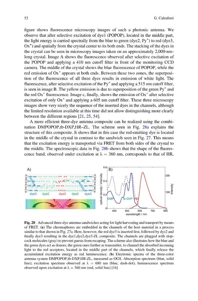
A more efficient three-dye antenna composite can be realized using the combination DMPOPOP,tb-DXP,HR–ZL. The scheme seen in Fig. 28a explains the
structure of this composite. It shows that in this case the red-emitting dye is located
in the middle of the crystal in contrast to the sandwich seen in Fig. 27. This means
that the excitation energy is transported via FRET from both sides of the crystal to
the middle. The spectroscopic data in Fig. 28b shows that the shape of the fluorescence band, observed under excitation at λ ¼ 360 nm, corresponds to that of HR,
Fig. 28 Advanced three-dye antenna sandwiches acting for light harvesting and transport by means
of FRET. (a) The chromophores are embedded in the channels of the host material in a process
similar to that shown in Fig. 27a. Here, however, the red dye3 is inserted first, followed by dye2 and
finally dye3 resulting in the dye1,dye2,dye3-ZL composite. The channels are plugged with stopcock molecules (gray) to prevent guests from escaping. The scheme also illustrates how the blue and
the green dyes act as donors, the green ones further as transmitter, to channel the absorbed incoming
light to the red acceptors, located in the middle part of the channels, which finally release the
accumulated excitation energy as red luminescence. (b) Electronic spectra of the three-color
antenna system DMPOPOP,tb-DXP,HR-ZL, measured as OGS. Absorption spectrum (blue, solid
line); excitation spectrum observed at λ ¼ 680 nm (blue, dash-dot); luminescence spectrum
observed upon excitation at λ ¼ 360 nm (red, solid line) [16]
52
G. Calzaferri
observe that after selective excitation of dye1 (POPOP), located in the middle part,
the light energy is carried spectrally from the blue to green (dye2, Py
+
) to red (dye3,
Ox
+
) and spatially from the crystal center to its both ends. The stacking of the dyes in
the crystal can be seen in microscopy images taken on an approximately 2,000-nmlong crystal. Image A shows the fluorescence observed after selective excitation of
the POPOP and applying a 410 nm cutoff filter in front of the monitoring CCD
camera. The middle of the crystal shows the blue fluorescence of POPOP, while the
red emission of Ox
+ appears at both ends. Between these two zones, the superposition of the fluorescence of all three dyes results in emission of white light. The
fluorescence, after selective excitation of the Py
+ and applying a 515 nm cutoff filter,
is seen in image B. The yellow emission is due to superposition of the green Py
+ and
the red Ox
+
fluorescence. Image c, finally, shows the emission of Ox
+ after selective
excitation of only Ox
+ and applying a 605 nm cutoff filter. These three microscopy
images show very nicely the sequence of the inserted dyes in the channels, although
the limited resolution available at this time did not allow distinguishing more clearly
between the different regions [21, 25, 54].
A more efficient three-dye antenna composite can be realized using the combination DMPOPOP,tb-DXP,HR–ZL. The scheme seen in Fig. 28a explains the
structure of this composite. It shows that in this case the red-emitting dye is located
in the middle of the crystal in contrast to the sandwich seen in Fig. 27. This means
that the excitation energy is transported via FRET from both sides of the crystal to
the middle. The spectroscopic data in Fig. 28b shows that the shape of the fluorescence band, observed under excitation at λ ¼ 360 nm, corresponds to that of HR,
Fig. 28 Advanced three-dye antenna sandwiches acting for light harvesting and transport by means
of FRET. (a) The chromophores are embedded in the channels of the host material in a process
similar to that shown in Fig. 27a. Here, however, the red dye3 is inserted first, followed by dye2 and
finally dye3 resulting in the dye1,dye2,dye3-ZL composite. The channels are plugged with stopcock molecules (gray) to prevent guests from escaping. The scheme also illustrates how the blue and
the green dyes act as donors, the green ones further as transmitter, to channel the absorbed incoming
light to the red acceptors, located in the middle part of the channels, which finally release the
accumulated excitation energy as red luminescence. (b) Electronic spectra of the three-color
antenna system DMPOPOP,tb-DXP,HR-ZL, measured as OGS. Absorption spectrum (blue, solid
line); excitation spectrum observed at λ ¼ 680 nm (blue, dash-dot); luminescence spectrum
observed upon excitation at λ ¼ 360 nm (red, solid line) [16]
52
G. Calzaferri