

lifetime of the RuBpy if the ΔE 1 was attributed to thermal access to the
3 LF state.
The fact that the observed emission lifetime is actually longer than RuBpy in
solution suggests that the barrier to access the
3 LF is sufficiently high as to prevent
any significant population of the state. The values of k 1 associated with RWLC-1 and
RWLC-2 are also several orders of magnitude lower than that of RuBpy in solution.
These data are consistent with a model in which a population of RuBpy is encapsulated within cavities of the RWLC-1 and RWLC-2 frameworks that restrict access to
the
3 LF state. Thus, the ΔE 1 value then represents the barrier to access
3 MLCT states
that are higher in energy than the emitting
3 MLCT manifold and the nearby fourth
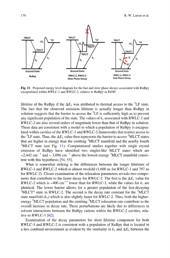
3 MLCT state (see Fig. 11). Computational studies together with single crystal
emission of RuBpy have identified two singlet-like MLCT states which are
~2,442 cm
À1 and ~ 3,096 cm
À1 above the lowest energy
3 MLCT manifold consistent with this hypothesis [54, 55].
What is somewhat striking is the differences between the longer lifetimes of
RWLC-1 and RWLC-2 which is almost twofold (1,600 ns for RWLC-1 and 797 ns
for RWLC-2). Closer examination of the relaxation parameters reveals two components that contribute to the faster decay for RWLC-2. The first is the ΔE 1 value for
RWLC-2 which is ~400 cm
À1 lower than for RWLC-1, while the values for k 1 are
identical. The lower barrier allows for a greater population of the fast-decaying
3 MLCT* state in RWLC-2. The second is the decay rate constant for the
3 MLCT
state manifold (k 1 ) which is also slightly faster for RWLC-2. Thus, both the higherenergy
3 MLCT population and the emitting
3 MLCT relaxation rate contribute to the
overall increase in decay rate. These perturbations are likely due to differences in
solvent interactions between the RuBpy cations within the RWLC-2 cavities, relative to RWLC-1 [62].
Examination of the decay parameters for short lifetime component for both
RWLC-1 and RWLC-2 is consistent with a population of RuBpy that is located in
a less confined environment as evident by the similarity in k 1 and ΔE 1 between the
Fig. 11 Proposed energy level diagram for the fast and slow phase decays associated with RuBpy
encapsulated within RWLC-1 and RWLC-2, relative to RuBpy in EtOH
170
R. W. Larsen et al.
3 LF state.
The fact that the observed emission lifetime is actually longer than RuBpy in
solution suggests that the barrier to access the
3 LF is sufficiently high as to prevent
any significant population of the state. The values of k 1 associated with RWLC-1 and
RWLC-2 are also several orders of magnitude lower than that of RuBpy in solution.
These data are consistent with a model in which a population of RuBpy is encapsulated within cavities of the RWLC-1 and RWLC-2 frameworks that restrict access to
the
3 LF state. Thus, the ΔE 1 value then represents the barrier to access
3 MLCT states
that are higher in energy than the emitting
3 MLCT manifold and the nearby fourth
3 MLCT state (see Fig. 11). Computational studies together with single crystal
emission of RuBpy have identified two singlet-like MLCT states which are
~2,442 cm
À1 and ~ 3,096 cm
À1 above the lowest energy
3 MLCT manifold consistent with this hypothesis [54, 55].
What is somewhat striking is the differences between the longer lifetimes of
RWLC-1 and RWLC-2 which is almost twofold (1,600 ns for RWLC-1 and 797 ns
for RWLC-2). Closer examination of the relaxation parameters reveals two components that contribute to the faster decay for RWLC-2. The first is the ΔE 1 value for
RWLC-2 which is ~400 cm
À1 lower than for RWLC-1, while the values for k 1 are
identical. The lower barrier allows for a greater population of the fast-decaying
3 MLCT* state in RWLC-2. The second is the decay rate constant for the
3 MLCT
state manifold (k 1 ) which is also slightly faster for RWLC-2. Thus, both the higherenergy
3 MLCT population and the emitting
3 MLCT relaxation rate contribute to the
overall increase in decay rate. These perturbations are likely due to differences in
solvent interactions between the RuBpy cations within the RWLC-2 cavities, relative to RWLC-1 [62].
Examination of the decay parameters for short lifetime component for both
RWLC-1 and RWLC-2 is consistent with a population of RuBpy that is located in
a less confined environment as evident by the similarity in k 1 and ΔE 1 between the
Fig. 11 Proposed energy level diagram for the fast and slow phase decays associated with RuBpy
encapsulated within RWLC-1 and RWLC-2, relative to RuBpy in EtOH
170
R. W. Larsen et al.