

Improvement of fine-grained and cohesive soils 165
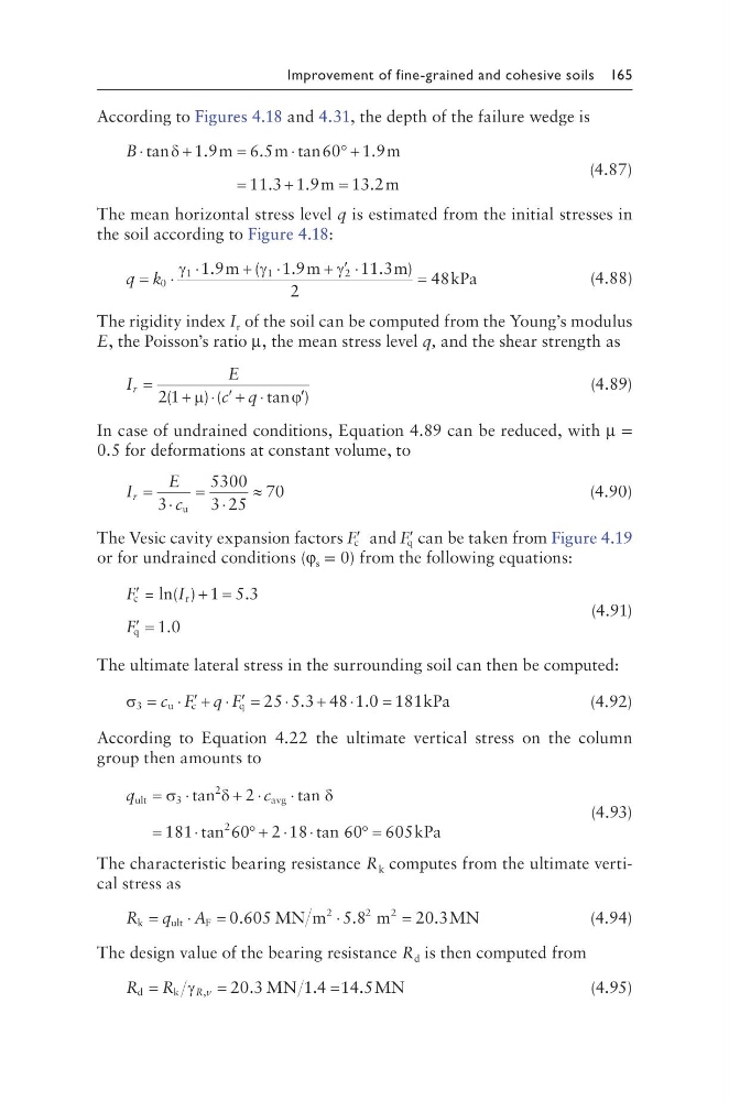
According to Figures 4.18 and 4.31, the depth of the failure wedge is
B ⋅
+
=
⋅
° +
=
+
=
tan
.
.
tan
.
.
.
.
δ 1 9
6 5
60 1 9
11 3 1 9
13 2
m
m
m
m
m
(4.87)
The mean horizontal stress level q is estimated from the initial stresses in
the soil according to Figure 4.18:
q k
= ⋅
⋅
+ ⋅
+ ′ ⋅
=
0
1
1
2
1 9
1 9
11 3
2
48
γ
γ
γ
.
(
.
. )
m
m
m
kPa
(4.88)
The rigidity index I r of the soil can be computed from the Young’s modulus
E, the Poisson’s ratio µ, the mean stress level q, and the shear strength as
I
E
c q
r =
+ ⋅ ′ + ⋅
′
2 1
(
) (
tan )
µ
ϕ
(4.89)
In case of undrained conditions, Equation 4.89 can be reduced, with µ =
0.5 for deformations at constant volume, to
I
E
c
r = ⋅
= ⋅
≈
3
5300
3 25
70
u
(4.90)
The Vesic cavity expansion factors ′
F c and ′
F q can be taken from Figure 4.19
or for undrained conditions (φ s = 0) from the following equations:
′
+ =
′ =
F
F
c
r
q
= ln( ) 1 5.3
1.0
I
(4.91)
The ultimate lateral stress in the surrounding soil can then be computed:
σ 3
u
c
q
kPa
= ⋅ ′ + ⋅ ′ =
⋅
+ ⋅
=
c
q
F
F 25 5 3 48 1 0 181
.
.
(4.92)
According to Equation 4.22 the ultimate vertical stress on the column
group then amounts to
q
c
ult
3
2
avg
2
tan
2
tan
181 tan 60 2 18 tan 60 605kPa
= ⋅
+ ⋅
⋅
=
⋅
° + ⋅ ⋅
° =
σ
δ
δ
(4.93)
The characteristic bearing resistance R k computes from the ultimate vertical stress as
R q
k
u lt
F
2
0.605 MN m
m
20.3MN
=
⋅
=
⋅
=
A
5 8
2
2
.
(4.94)
The design value of the bearing resistance R d is then computed from
R R R v
d
k
MN
MN
=
=
=
γ ,
.
.
.
20 3
14 14 5
(4.95)
According to Figures 4.18 and 4.31, the depth of the failure wedge is
B ⋅
+
=
⋅
° +
=
+
=
tan
.
.
tan
.
.
.
.
δ 1 9
6 5
60 1 9
11 3 1 9
13 2
m
m
m
m
m
(4.87)
The mean horizontal stress level q is estimated from the initial stresses in
the soil according to Figure 4.18:
q k
= ⋅
⋅
+ ⋅
+ ′ ⋅
=
0
1
1
2
1 9
1 9
11 3
2
48
γ
γ
γ
.
(
.
. )
m
m
m
kPa
(4.88)
The rigidity index I r of the soil can be computed from the Young’s modulus
E, the Poisson’s ratio µ, the mean stress level q, and the shear strength as
I
E
c q
r =
+ ⋅ ′ + ⋅
′
2 1
(
) (
tan )
µ
ϕ
(4.89)
In case of undrained conditions, Equation 4.89 can be reduced, with µ =
0.5 for deformations at constant volume, to
I
E
c
r = ⋅
= ⋅
≈
3
5300
3 25
70
u
(4.90)
The Vesic cavity expansion factors ′
F c and ′
F q can be taken from Figure 4.19
or for undrained conditions (φ s = 0) from the following equations:
′
+ =
′ =
F
F
c
r
q
= ln( ) 1 5.3
1.0
I
(4.91)
The ultimate lateral stress in the surrounding soil can then be computed:
σ 3
u
c
q
kPa
= ⋅ ′ + ⋅ ′ =
⋅
+ ⋅
=
c
q
F
F 25 5 3 48 1 0 181
.
.
(4.92)
According to Equation 4.22 the ultimate vertical stress on the column
group then amounts to
q
c
ult
3
2
avg
2
tan
2
tan
181 tan 60 2 18 tan 60 605kPa
= ⋅
+ ⋅
⋅
=
⋅
° + ⋅ ⋅
° =
σ
δ
δ
(4.93)
The characteristic bearing resistance R k computes from the ultimate vertical stress as
R q
k
u lt
F
2
0.605 MN m
m
20.3MN
=
⋅
=
⋅
=
A
5 8
2
2
.
(4.94)
The design value of the bearing resistance R d is then computed from
R R R v
d
k
MN
MN
=
=
=
γ ,
.
.
.
20 3
14 14 5
(4.95)