

164 Ground improvement by deep vibratory methods
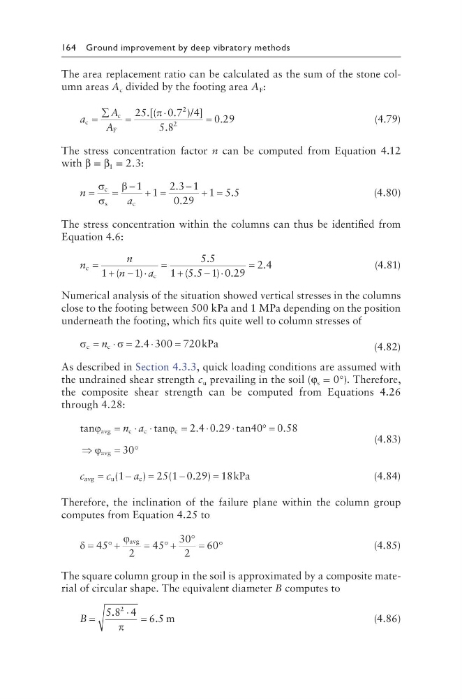
The area replacement ratio can be calculated as the sum of the stone column areas A c divided by the footing area A F :
a
A
A
c
c
F
/
=
∑
=
⋅
=
25
0 7 4
5 8
0 29
2
2
.[(
. ) ]
.
.
π
(4.79)
The stress concentration factor n can be computed from Equation 4.12
with β = β 1 = 2.3:
n
a
=
=
− + =
− + =
σ
σ
β
c
s
c
1 1
2 3 1
0 29
1 5 5
.
.
.
(4.80)
The stress concentration within the columns can thus be identified from
Equation 4.6:
n
n
n
a
c
c
= + − ⋅
= +
− ⋅
=
1
1
5 5
1 5 5 1 0 29
2 4
(
)
.
( .
) .
.
(4.81)
Numerical analysis of the situation showed vertical stresses in the columns
close to the footing between 500 kPa and 1 MPa depending on the position
underneath the footing, which fits quite well to column stresses of
σ
σ
c
c
2.4 300 720kPa
= ⋅ =
⋅
=
n
(4.82)
As described in Section 4.3.3, quick loading conditions are assumed with
the undrained shear strength c u prevailing in the soil (φ s = 0°). Therefore,
the composite shear strength can be computed from Equations 4.26
through 4.28:
tan
t an
2.4 0.29 tan40 0.58
avg
c
c
c
avg
ϕ
ϕ
ϕ
= ⋅ ⋅
=
⋅
⋅
° =
⇒
= °
n a
30
(4.83)
c
c
a
avg
u
c
(1
) 25(1 0.29) 18kPa
=
−
=
−
=
(4.84)
Therefore, the inclination of the failure plane within the column group
computes from Equation 4.25 to
δ
ϕ
=
+
45
45
30
2
60
°
= ° +
° = °
avg
2
(4.85)
The square column group in the soil is approximated by a composite material of circular shape. The equivalent diameter B computes to
B =
⋅ =
5 8 4 6 5
2
.
.
π
m
(4.86)
The area replacement ratio can be calculated as the sum of the stone column areas A c divided by the footing area A F :
a
A
A
c
c
F
/
=
∑
=
⋅
=
25
0 7 4
5 8
0 29
2
2
.[(
. ) ]
.
.
π
(4.79)
The stress concentration factor n can be computed from Equation 4.12
with β = β 1 = 2.3:
n
a
=
=
− + =
− + =
σ
σ
β
c
s
c
1 1
2 3 1
0 29
1 5 5
.
.
.
(4.80)
The stress concentration within the columns can thus be identified from
Equation 4.6:
n
n
n
a
c
c
= + − ⋅
= +
− ⋅
=
1
1
5 5
1 5 5 1 0 29
2 4
(
)
.
( .
) .
.
(4.81)
Numerical analysis of the situation showed vertical stresses in the columns
close to the footing between 500 kPa and 1 MPa depending on the position
underneath the footing, which fits quite well to column stresses of
σ
σ
c
c
2.4 300 720kPa
= ⋅ =
⋅
=
n
(4.82)
As described in Section 4.3.3, quick loading conditions are assumed with
the undrained shear strength c u prevailing in the soil (φ s = 0°). Therefore,
the composite shear strength can be computed from Equations 4.26
through 4.28:
tan
t an
2.4 0.29 tan40 0.58
avg
c
c
c
avg
ϕ
ϕ
ϕ
= ⋅ ⋅
=
⋅
⋅
° =
⇒
= °
n a
30
(4.83)
c
c
a
avg
u
c
(1
) 25(1 0.29) 18kPa
=
−
=
−
=
(4.84)
Therefore, the inclination of the failure plane within the column group
computes from Equation 4.25 to
δ
ϕ
=
+
45
45
30
2
60
°
= ° +
° = °
avg
2
(4.85)
The square column group in the soil is approximated by a composite material of circular shape. The equivalent diameter B computes to
B =
⋅ =
5 8 4 6 5
2
.
.
π
m
(4.86)