

126 Ground improvement by deep vibratory methods
of column and soil, comes an expression for the improvement factor β as
the ratio of the settlement of the untreated (s) and the improved ground (s i ):
β
µ
µ
= = +
⋅
+
⋅
−
s
s
A
A
f
A A
K f
A A
i
c
s
c
ac
s
c
/
/
/
1
1 2
1
( ,
)
( ,
)
(4.13)
with
f
A A
A A
A A
( ,
)
(
) (
)
µ
µ
µ
µ
µ
µ
s
c
s
s
s
s
c
s
c
/
/
/
=
−
− −
⋅
−
⋅ −
−
+
1
1
2
1 2
1
1 2
2
2
(4.14)
and
K ac
2
c
= tan (45
/2)
° − ϕ
(4.15)
In these equations the notations of the unit cell from Figure 4.8 are used;
with φ c representing the friction angle of the column material and µ s the
Poisson’s ratio of the soil.
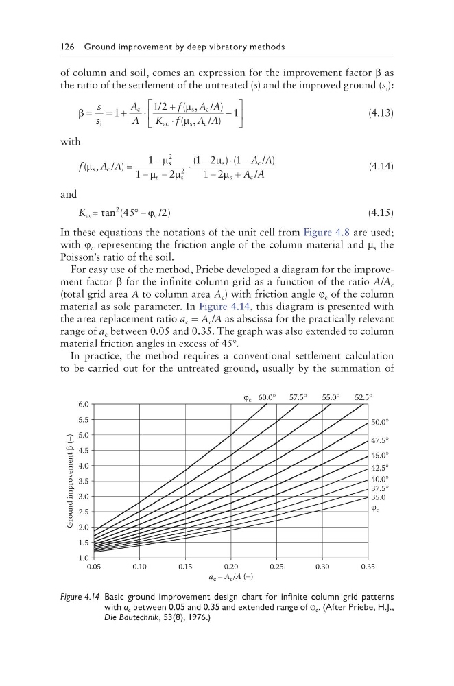
For easy use of the method, Priebe developed a diagram for the improvement factor β for the infinite column grid as a function of the ratio A/A c
(total grid area A to column area A c ) with friction angle φ c of the column
material as sole parameter. In Figure 4.14, this diagram is presented with
the area replacement ratio a c = A c /A as abscissa for the practically relevant
range of a c between 0.05 and 0.35. The graph was also extended to column
material friction angles in excess of 45°.
In practice, the method requires a conventional settlement calculation
to be carried out for the untreated ground, usually by the summation of
a c = A c /A (−)
1.0
1.5
2.0
2.5
3.0
3.5
4.0
4.5
5.0
5.5
6.0
Ground improvement β
(−)
50.0°
52.5°
55.0°
57.5°
60.0°
φ c
47.5°
45.0°
42.5°
40.0°
37.5°
35.0
φ c
0.35
0.05
0.10
0.15
0.20
0.25
0.30
Figure 4.14 Basic ground improvement design chart for infinite column grid patterns
with a c between 0.05 and 0.35 and extended range of φ c . (After Priebe, H.J.,
Die Bautechnik, 53(8), 1976.)
of column and soil, comes an expression for the improvement factor β as
the ratio of the settlement of the untreated (s) and the improved ground (s i ):
β
µ
µ
= = +
⋅
+
⋅
−
s
s
A
A
f
A A
K f
A A
i
c
s
c
ac
s
c
/
/
/
1
1 2
1
( ,
)
( ,
)
(4.13)
with
f
A A
A A
A A
( ,
)
(
) (
)
µ
µ
µ
µ
µ
µ
s
c
s
s
s
s
c
s
c
/
/
/
=
−
− −
⋅
−
⋅ −
−
+
1
1
2
1 2
1
1 2
2
2
(4.14)
and
K ac
2
c
= tan (45
/2)
° − ϕ
(4.15)
In these equations the notations of the unit cell from Figure 4.8 are used;
with φ c representing the friction angle of the column material and µ s the
Poisson’s ratio of the soil.
For easy use of the method, Priebe developed a diagram for the improvement factor β for the infinite column grid as a function of the ratio A/A c
(total grid area A to column area A c ) with friction angle φ c of the column
material as sole parameter. In Figure 4.14, this diagram is presented with
the area replacement ratio a c = A c /A as abscissa for the practically relevant
range of a c between 0.05 and 0.35. The graph was also extended to column
material friction angles in excess of 45°.
In practice, the method requires a conventional settlement calculation
to be carried out for the untreated ground, usually by the summation of
a c = A c /A (−)
1.0
1.5
2.0
2.5
3.0
3.5
4.0
4.5
5.0
5.5
6.0
Ground improvement β
(−)
50.0°
52.5°
55.0°
57.5°
60.0°
φ c
47.5°
45.0°
42.5°
40.0°
37.5°
35.0
φ c
0.35
0.05
0.10
0.15
0.20
0.25
0.30
Figure 4.14 Basic ground improvement design chart for infinite column grid patterns
with a c between 0.05 and 0.35 and extended range of φ c . (After Priebe, H.J.,
Die Bautechnik, 53(8), 1976.)