

Improvement of fine-grained and cohesive soils 125
Almost all approaches to calculating the settlement reduction by the use
of vibro stone columns are based on the infinite column grid. Few deal with
the quantitative behavior of column groups, and all make major simplifying
assumptions. Investigations of the settlement behavior of isolated columns
are rare and of little practical use. Frequently, however, single-column load
testing is performed as a quality control measure and to predict settlement
performance of structures, a method requiring particularly careful evaluation (see Section 4.4).
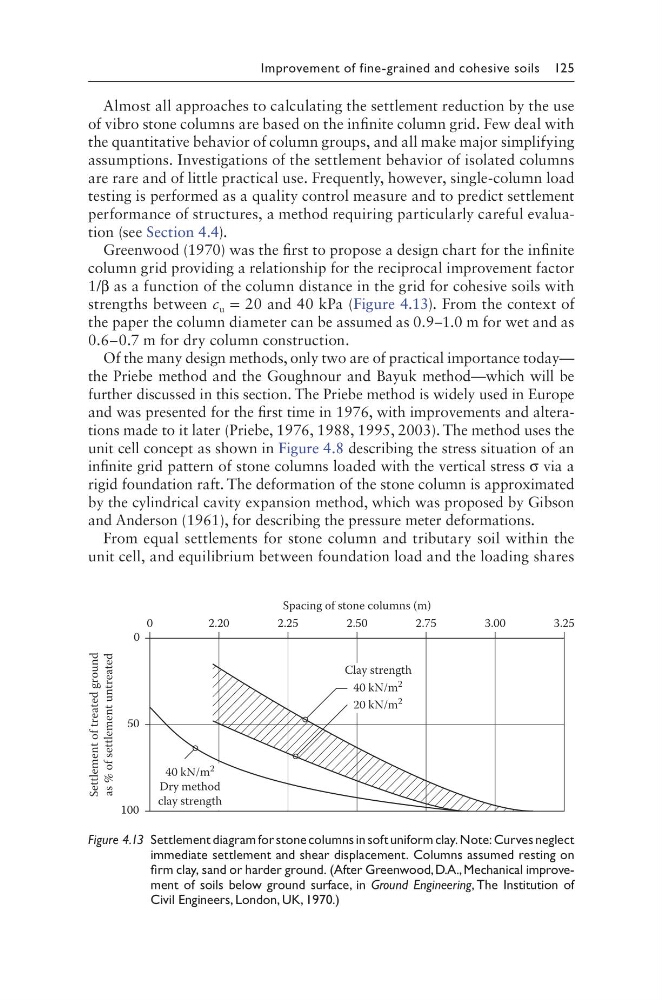
Greenwood (1970) was the first to propose a design chart for the infinite
column grid providing a relationship for the reciprocal improvement factor
1/β as a function of the column distance in the grid for cohesive soils with
strengths between c u = 20 and 40 kPa (Figure 4.13). From the context of
the paper the column diameter can be assumed as 0.9–1.0 m for wet and as
0.6–0.7 m for dry column construction.
Of the many design methods, only two are of practical importance today—
the Priebe method and the Goughnour and Bayuk method—which will be
further discussed in this section. The Priebe method is widely used in Europe
and was presented for the first time in 1976, with improvements and alterations made to it later (Priebe, 1976, 1988, 1995, 2003). The method uses the
unit cell concept as shown in Figure 4.8 describing the stress situation of an
infinite grid pattern of stone columns loaded with the vertical stress σ via a
rigid foundation raft. The deformation of the stone column is approximated
by the cylindrical cavity expansion method, which was proposed by Gibson
and Anderson (1961), for describing the pressure meter deformations.
From equal settlements for stone column and tributary soil within the
unit cell, and equilibrium between foundation load and the loading shares
2.20
2.25
2.50
2.75
3.00
3.25
0
100
50
0
Spacing of stone columns (m)
Clay strength
40 kN/m 2
20 kN/m
2
40 kN/m 2
Dry method
clay strength
Settlement of treated ground
as %
of settlement untreated
Figure 4.13 Settlement diagram for stone columns in soft uniform clay. Note: Curves neglect
immediate settlement and shear displacement. Columns assumed resting on
firm clay, sand or harder ground. (After Greenwood, D.A., Mechanical improvement of soils below ground surface, in Ground Engineering, The Institution of
Civil Engineers, London, UK, 1970.)
Almost all approaches to calculating the settlement reduction by the use
of vibro stone columns are based on the infinite column grid. Few deal with
the quantitative behavior of column groups, and all make major simplifying
assumptions. Investigations of the settlement behavior of isolated columns
are rare and of little practical use. Frequently, however, single-column load
testing is performed as a quality control measure and to predict settlement
performance of structures, a method requiring particularly careful evaluation (see Section 4.4).
Greenwood (1970) was the first to propose a design chart for the infinite
column grid providing a relationship for the reciprocal improvement factor
1/β as a function of the column distance in the grid for cohesive soils with
strengths between c u = 20 and 40 kPa (Figure 4.13). From the context of
the paper the column diameter can be assumed as 0.9–1.0 m for wet and as
0.6–0.7 m for dry column construction.
Of the many design methods, only two are of practical importance today—
the Priebe method and the Goughnour and Bayuk method—which will be
further discussed in this section. The Priebe method is widely used in Europe
and was presented for the first time in 1976, with improvements and alterations made to it later (Priebe, 1976, 1988, 1995, 2003). The method uses the
unit cell concept as shown in Figure 4.8 describing the stress situation of an
infinite grid pattern of stone columns loaded with the vertical stress σ via a
rigid foundation raft. The deformation of the stone column is approximated
by the cylindrical cavity expansion method, which was proposed by Gibson
and Anderson (1961), for describing the pressure meter deformations.
From equal settlements for stone column and tributary soil within the
unit cell, and equilibrium between foundation load and the loading shares
2.20
2.25
2.50
2.75
3.00
3.25
0
100
50
0
Spacing of stone columns (m)
Clay strength
40 kN/m 2
20 kN/m
2
40 kN/m 2
Dry method
clay strength
Settlement of treated ground
as %
of settlement untreated
Figure 4.13 Settlement diagram for stone columns in soft uniform clay. Note: Curves neglect
immediate settlement and shear displacement. Columns assumed resting on
firm clay, sand or harder ground. (After Greenwood, D.A., Mechanical improvement of soils below ground surface, in Ground Engineering, The Institution of
Civil Engineers, London, UK, 1970.)