

Three factors have a major influence on the quality of digital orthophotos—two
geometrically and one radiometrically. There are three basic inputs for the production of digital orthophotos:
• Digital aerial imagery.
• External orientations of aerial images.
• Digital elevation models.
Digital images were produced as a result of the aerial photography flights, and
comprehensive block-wise color balancing (project-based color balancing (PBCB))
was already made at the Level 03 UltraMap image-processing phase. The other two
inputs, exterior orientations of images and ortho DEM, affected directly the geometric accuracy of the orthorectified images. There were practically no other relevant
factors affecting the quality of orthorectification using the OrthoMaster
orthorectification software.
The ortho DEMs were imported to OrthoMaster together with the aerial images
and the Match-AT project files. The DEM files had the mass points and, whenever
necessary, separately measured break lines in different layers. The output footprint
of each orthorectified image was generated to ensure that the center of each frame
was utilized.
On completion of the rectification process, a visual inspection of the imagery was
undertaken to identify distortions or other anomalies. The geometric accuracy of the
orthorectified images was later reviewed using ground control points and measured
checkpoints. A visual inspection was undertaken at joints between adjacent rectified
images within and between the flight lines.
On completion of the rectification process, first, a visual inspection of all ortho
product tiles was undertaken to identify distortions or other anomalies. Where
distortions or other anomalies were detected, necessary correction precautions
were taken, beginning with the DEM controls, corrections, re-rectification, and, if
necessary, re-AT. The geometric accuracy of the orthorectified images was inspected
using two approaches, namely, internal quality control (IQC) and external quality
control (EQC).
During the IQC process, sample tiles were defined over the block’s edge and in
the block. At least 10% of the ortho tiles were inspected by defining sharp objects
such as building corners, road cross-sections, and electric poles. The coordinates of
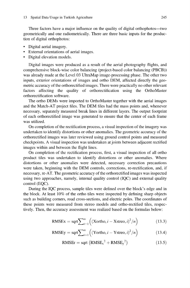
these points were measured from stereo models and ortho-rectified tiles, respectively. Then, the accuracy assessment was realized based on the formulas below:
RMSEx ¼ sqrt
X n
i¼1
Xortho, i À Xstreo, i
ð
Þ
2 =n
ð13:3Þ
RMSEy ¼ sqrt
X n
i¼1
Yortho, i À Ystreo, i
ð
Þ
2 =n
ð13:4Þ
RMSEr ¼ sqrt RMSE x
2
þ RMSE y
2
À
Á
ð13:5Þ
13 Spatial Data Usage in Turkish Agriculture
245
geometrically and one radiometrically. There are three basic inputs for the production of digital orthophotos:
• Digital aerial imagery.
• External orientations of aerial images.
• Digital elevation models.
Digital images were produced as a result of the aerial photography flights, and
comprehensive block-wise color balancing (project-based color balancing (PBCB))
was already made at the Level 03 UltraMap image-processing phase. The other two
inputs, exterior orientations of images and ortho DEM, affected directly the geometric accuracy of the orthorectified images. There were practically no other relevant
factors affecting the quality of orthorectification using the OrthoMaster
orthorectification software.
The ortho DEMs were imported to OrthoMaster together with the aerial images
and the Match-AT project files. The DEM files had the mass points and, whenever
necessary, separately measured break lines in different layers. The output footprint
of each orthorectified image was generated to ensure that the center of each frame
was utilized.
On completion of the rectification process, a visual inspection of the imagery was
undertaken to identify distortions or other anomalies. The geometric accuracy of the
orthorectified images was later reviewed using ground control points and measured
checkpoints. A visual inspection was undertaken at joints between adjacent rectified
images within and between the flight lines.
On completion of the rectification process, first, a visual inspection of all ortho
product tiles was undertaken to identify distortions or other anomalies. Where
distortions or other anomalies were detected, necessary correction precautions
were taken, beginning with the DEM controls, corrections, re-rectification, and, if
necessary, re-AT. The geometric accuracy of the orthorectified images was inspected
using two approaches, namely, internal quality control (IQC) and external quality
control (EQC).
During the IQC process, sample tiles were defined over the block’s edge and in
the block. At least 10% of the ortho tiles were inspected by defining sharp objects
such as building corners, road cross-sections, and electric poles. The coordinates of
these points were measured from stereo models and ortho-rectified tiles, respectively. Then, the accuracy assessment was realized based on the formulas below:
RMSEx ¼ sqrt
X n
i¼1
Xortho, i À Xstreo, i
ð
Þ
2 =n
ð13:3Þ
RMSEy ¼ sqrt
X n
i¼1
Yortho, i À Ystreo, i
ð
Þ
2 =n
ð13:4Þ
RMSEr ¼ sqrt RMSE x
2
þ RMSE y
2
À
Á
ð13:5Þ
13 Spatial Data Usage in Turkish Agriculture
245