

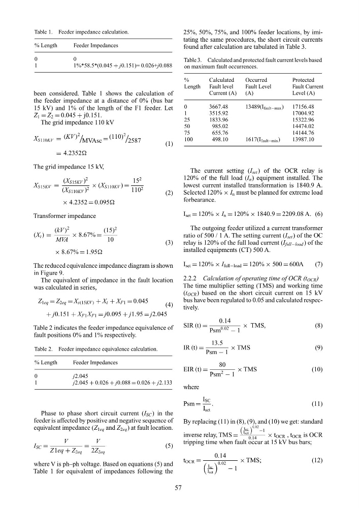
Table 1. Feeder impedance calculation.
% Length
Feeder Impedances
0
0
1
1%*58.5*(0.045 + j0.151)= 0.026+j0.088
been considered. Table 1 shows the calculation of
the feeder impedance at a distance of 0% (bus bar
15 kV) and 1% of the length of the F1 feeder. Let
Z 1 = Z 2 = 0.045 + j0.151.
The grid impedance 110 kV
X S110KV = (KV )
2
MVAsc = (110)
2
2587
(1)
= 4.2352
The grid impedance 15 kV,
X S15KV =
(X S15KV )
2
(X S110KV ) 2 × (X S110KV ) =
15
2
110 2
(2)
× 4.2352 = 0.095
Transformer impedance
(X t ) =
(kV )
2
MVA
× 8.67% =
(15)
2
10
(3)
× 8.67% = 1.95
The reduced equivalence impedance diagram is shown
in Figure 9.
The equivalent of impedance in the fault location
was calculated in series,
Z 1eq = Z 2eq = X s(15KV ) + X t + X F1 = 0.045
(4)
+ j0.151 + X F1 X F1 = j0.095 + j1.95 = j2.045
Table 2 indicates the feeder impedance equivalence of
fault positions 0% and 1% respectively.
Table 2. Feeder impedance equivalence calculation.
% Length
Feeder Impedances
0
j2.045
1
j2.045 + 0.026 + j0.088 = 0.026 + j2.133
Phase to phase short circuit current (I SC ) in the
feeder is affected by positive and negative sequence of
equivalent impedance (Z 1eq and Z 2eq ) at fault location.
I SC =
V
Z1eq + Z 2eq
=
V
2Z 2eq
(5)
where V is ph–ph voltage. Based on equations (5) and
Table 1 for equivalent of impedances following the
25%, 50%, 75%, and 100% feeder locations, by imitating the same procedures, the short circuit currents
found after calculation are tabulated in Table 3.
Table 3. Calculated and protected fault current levels based
on maximum fault occurrences.
%
Calculated
Occurred
Protected
Length
Fault level
Fault Level
Fault Current
Current (A)
(A)
Level (A)
0
3667.48
13489(I fault−max )
17156.48
1
3515.92
17004.92
25
1833.96
15322.96
50
985.02
14474.02
75
655.76
14144.76
100
498.10
1617(I fault−min )
13987.10
The current setting (I set ) of the OCR relay is
120% of the full load (I n ) equipment installed. The
lowest current installed transformation is 1840.9 A.
Selected 120% × I n must be planned for extreme load
forbearance.
I set = 120% × I n = 120% × 1840.9 = 2209.08 A. (6)
The outgoing feeder utilized a current transformer
ratio of 500 / 1 A. The setting current (I set ) of the OC
relay is 120% of the full load current (I full−load ) of the
installed equipments (CT) 500 A.
I set = 120% × I full−load = 120% × 500 = 600A
(7)
2.2.2 Calculation of operating time of OCR (t OCR )
The time multiplier setting (TMS) and working time
(t OCR ) based on the short circuit current on 15 kV
bus have been regulated to 0.05 and calculated respectively.
SIR (t) =
0.14
Psm
0.02
− 1
× TMS,
(8)
IR (t) =
13.5
Psm − 1
× TMS
(9)
EIR (t) =
80
Psm
2
− 1
× TMS
(10)
where
Psm =
I SC
I set
.
(11)
By replacing (11) in (8), (9), and (10) we get: standard
inverse relay, TMS =
Isc
I set
0.02 −1
0.14
× t OCR , t OCR is OCR
tripping time when fault occur at 15 kV bus bars;
t OCR =
0.14
Isc
Iset
0.02 − 1
× TMS;
(12)
57
% Length
Feeder Impedances
0
0
1
1%*58.5*(0.045 + j0.151)= 0.026+j0.088
been considered. Table 1 shows the calculation of
the feeder impedance at a distance of 0% (bus bar
15 kV) and 1% of the length of the F1 feeder. Let
Z 1 = Z 2 = 0.045 + j0.151.
The grid impedance 110 kV
X S110KV = (KV )
2
MVAsc = (110)
2
2587
(1)
= 4.2352
The grid impedance 15 kV,
X S15KV =
(X S15KV )
2
(X S110KV ) 2 × (X S110KV ) =
15
2
110 2
(2)
× 4.2352 = 0.095
Transformer impedance
(X t ) =
(kV )
2
MVA
× 8.67% =
(15)
2
10
(3)
× 8.67% = 1.95
The reduced equivalence impedance diagram is shown
in Figure 9.
The equivalent of impedance in the fault location
was calculated in series,
Z 1eq = Z 2eq = X s(15KV ) + X t + X F1 = 0.045
(4)
+ j0.151 + X F1 X F1 = j0.095 + j1.95 = j2.045
Table 2 indicates the feeder impedance equivalence of
fault positions 0% and 1% respectively.
Table 2. Feeder impedance equivalence calculation.
% Length
Feeder Impedances
0
j2.045
1
j2.045 + 0.026 + j0.088 = 0.026 + j2.133
Phase to phase short circuit current (I SC ) in the
feeder is affected by positive and negative sequence of
equivalent impedance (Z 1eq and Z 2eq ) at fault location.
I SC =
V
Z1eq + Z 2eq
=
V
2Z 2eq
(5)
where V is ph–ph voltage. Based on equations (5) and
Table 1 for equivalent of impedances following the
25%, 50%, 75%, and 100% feeder locations, by imitating the same procedures, the short circuit currents
found after calculation are tabulated in Table 3.
Table 3. Calculated and protected fault current levels based
on maximum fault occurrences.
%
Calculated
Occurred
Protected
Length
Fault level
Fault Level
Fault Current
Current (A)
(A)
Level (A)
0
3667.48
13489(I fault−max )
17156.48
1
3515.92
17004.92
25
1833.96
15322.96
50
985.02
14474.02
75
655.76
14144.76
100
498.10
1617(I fault−min )
13987.10
The current setting (I set ) of the OCR relay is
120% of the full load (I n ) equipment installed. The
lowest current installed transformation is 1840.9 A.
Selected 120% × I n must be planned for extreme load
forbearance.
I set = 120% × I n = 120% × 1840.9 = 2209.08 A. (6)
The outgoing feeder utilized a current transformer
ratio of 500 / 1 A. The setting current (I set ) of the OC
relay is 120% of the full load current (I full−load ) of the
installed equipments (CT) 500 A.
I set = 120% × I full−load = 120% × 500 = 600A
(7)
2.2.2 Calculation of operating time of OCR (t OCR )
The time multiplier setting (TMS) and working time
(t OCR ) based on the short circuit current on 15 kV
bus have been regulated to 0.05 and calculated respectively.
SIR (t) =
0.14
Psm
0.02
− 1
× TMS,
(8)
IR (t) =
13.5
Psm − 1
× TMS
(9)
EIR (t) =
80
Psm
2
− 1
× TMS
(10)
where
Psm =
I SC
I set
.
(11)
By replacing (11) in (8), (9), and (10) we get: standard
inverse relay, TMS =
Isc
I set
0.02 −1
0.14
× t OCR , t OCR is OCR
tripping time when fault occur at 15 kV bus bars;
t OCR =
0.14
Isc
Iset
0.02 − 1
× TMS;
(12)
57