

d. Inverter
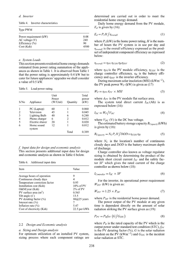
Table 4. Inverter characteristics
Type PWM
Power requirement (kW)
0.08
AC voltage (V)
240
Efficiency (%)
90
Cost (Ksh)
4500
e. System Loads
This section presents residential home energy demands
estimated from power rating summation of the appliances as shown in Table 1. It is observed from Table 1
that the power rating is approximately 0.4 kW but to
cater for future appliances’ upgrades we shall consider
a value of 0.5 kW.
Table 5. Load power rating.
Unit
Total
Power
power
S/No
Appliance
(W/Unit)
Quantity
(kW)
1
PC (Laptop)
60
1
0.060
2
Television
45
1
0.045
3
Lighting Bulb
40
6
0.240
4
Phone charger
6
2
0.012
5
Electric shaver
20
1
0.020
6
Home sound
12
1
0.012
system
Total
0.389
f. Input data for design and economic analysis
This section presents additional input data for design
and economic analysis as shown in Table 6 below.
Table 6. Additional input data
Item
Value
Average hours of operation
9
Continuous cloudy days
4
Temperature correction factor
0.95
Installation cost (Ksh)
10% of PV
O&M/year (Ksh)
2% of PV
PV surface area (m
2 )
0.565
Tilt angle (C)
13.5
PV derating factor (%)
80@25 years
Interest rate (%)
7
Inflation rate (%)
5.47
Cost of electricity (Ksh)
22.5 per kWh
2.2 Design and Economic analysis
a. Sizing and Design analysis
For optimum utilization of an installed PV system,
sizing process where each component ratings are
determined are carried out in order to meet the
residential home energy demand.
Daily home energy demand from the PV module,
E d is given by (16):
E d = P r H
η overall
(1)
where P r (kW) is the home power rating, H is the number of hours the PV system is in use per day and
η overall is the overall efficiency expressed as the product of independent component efficiency as expressed
below:
η overall = η PV η CON η B η INV
(2)
where η PV is the PV module efficiency, η CON is the
charge controller efficiency, η B is the battery efficiency and η INV is the inverter efficiency.
During maximum solar insolation (MSI) (kWm
−2 ),
the PV peak power W P (kW) is given as (17)
W P = η PV A PV × MSI
(3)
where A PV is the PV module flat surface area.
The system total direct current I DC (Ah) is as
expressed below (16):
I DC = W P
V DC
(4)
where V DC (V) is the DC bus voltage.
The estimated battery storage capacity B Capacity (kWh)
is given by (18):
B Capacity = N C P r H
DOD×η CON η B
(5)
where N C is the location’s number of continuous
cloudy days and DOD is the battery maximum depth
of discharge.
Charge controller also known as voltage regulator
sizing is obtained by determining the product of the
module short circuit current I SC and the safety factor SF which gives the rated current of the charge
controller as shown below (18):
I Controller = I SC × SF
(6)
For the inverter, its operational power requirement
W INV (kW) is given as:
W INV = 1.25 × P DF
(7)
where P DF is the residential home power demand.
The power output of the PV module at any given
time is dependent directly on the amount of solar
radiation striking the PV surface given as (19):
P PV = P R f PV
G
G STC
(8)
where P R is the rated capacity of the PV which is the
output power under standard test condition (STC), f PV
is the PV derating factor (%), G is the solar radiation
incident on the PV (kWm
−2 ) and G STC is the incident
solar radiation at STC.
238
Table 4. Inverter characteristics
Type PWM
Power requirement (kW)
0.08
AC voltage (V)
240
Efficiency (%)
90
Cost (Ksh)
4500
e. System Loads
This section presents residential home energy demands
estimated from power rating summation of the appliances as shown in Table 1. It is observed from Table 1
that the power rating is approximately 0.4 kW but to
cater for future appliances’ upgrades we shall consider
a value of 0.5 kW.
Table 5. Load power rating.
Unit
Total
Power
power
S/No
Appliance
(W/Unit)
Quantity
(kW)
1
PC (Laptop)
60
1
0.060
2
Television
45
1
0.045
3
Lighting Bulb
40
6
0.240
4
Phone charger
6
2
0.012
5
Electric shaver
20
1
0.020
6
Home sound
12
1
0.012
system
Total
0.389
f. Input data for design and economic analysis
This section presents additional input data for design
and economic analysis as shown in Table 6 below.
Table 6. Additional input data
Item
Value
Average hours of operation
9
Continuous cloudy days
4
Temperature correction factor
0.95
Installation cost (Ksh)
10% of PV
O&M/year (Ksh)
2% of PV
PV surface area (m
2 )
0.565
Tilt angle (C)
13.5
PV derating factor (%)
80@25 years
Interest rate (%)
7
Inflation rate (%)
5.47
Cost of electricity (Ksh)
22.5 per kWh
2.2 Design and Economic analysis
a. Sizing and Design analysis
For optimum utilization of an installed PV system,
sizing process where each component ratings are
determined are carried out in order to meet the
residential home energy demand.
Daily home energy demand from the PV module,
E d is given by (16):
E d = P r H
η overall
(1)
where P r (kW) is the home power rating, H is the number of hours the PV system is in use per day and
η overall is the overall efficiency expressed as the product of independent component efficiency as expressed
below:
η overall = η PV η CON η B η INV
(2)
where η PV is the PV module efficiency, η CON is the
charge controller efficiency, η B is the battery efficiency and η INV is the inverter efficiency.
During maximum solar insolation (MSI) (kWm
−2 ),
the PV peak power W P (kW) is given as (17)
W P = η PV A PV × MSI
(3)
where A PV is the PV module flat surface area.
The system total direct current I DC (Ah) is as
expressed below (16):
I DC = W P
V DC
(4)
where V DC (V) is the DC bus voltage.
The estimated battery storage capacity B Capacity (kWh)
is given by (18):
B Capacity = N C P r H
DOD×η CON η B
(5)
where N C is the location’s number of continuous
cloudy days and DOD is the battery maximum depth
of discharge.
Charge controller also known as voltage regulator
sizing is obtained by determining the product of the
module short circuit current I SC and the safety factor SF which gives the rated current of the charge
controller as shown below (18):
I Controller = I SC × SF
(6)
For the inverter, its operational power requirement
W INV (kW) is given as:
W INV = 1.25 × P DF
(7)
where P DF is the residential home power demand.
The power output of the PV module at any given
time is dependent directly on the amount of solar
radiation striking the PV surface given as (19):
P PV = P R f PV
G
G STC
(8)
where P R is the rated capacity of the PV which is the
output power under standard test condition (STC), f PV
is the PV derating factor (%), G is the solar radiation
incident on the PV (kWm
−2 ) and G STC is the incident
solar radiation at STC.
238