

Flow in pressurized conduits 69
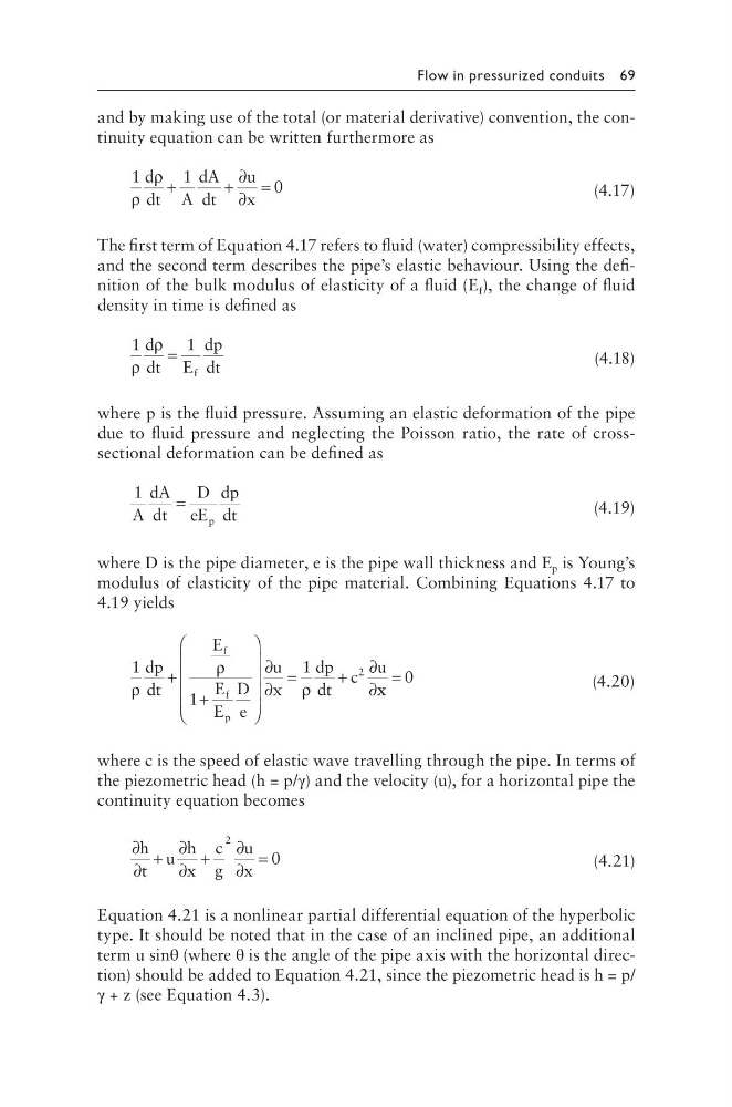
and by making use of the total (or material derivative) convention, the continuity equation can be written furthermore as
1
1
0
ρ
ρ
d
dt A
dA
dt
u
x
+
+
∂
∂
=
(4.17)
The first term of Equation 4.17 refers to fluid (water) compressibility effects,
and the second term describes the pipe’s elastic behaviour. Using the definition of the bulk modulus of elasticity of a fluid (E f ), the change of fluid
density in time is defined as
1
1
ρ
ρ
d
dt E
dp
dt
f
=
(4.18)
where p is the fluid pressure. Assuming an elastic deformation of the pipe
due to fluid pressure and neglecting the Poisson ratio, the rate of crosssectional deformation can be defined as
1
A
dA
dt
D
eE
dp
dt
p
=
(4.19)
where D is the pipe diameter, e is the pipe wall thickness and E p is Young’s
modulus of elasticity of the pipe material. Combining Equations 4.17 to
4.19 yields
1
1
1
2
ρ
ρ
ρ
dp
dt
E
E
E
D
e
u
x
dp
dt
c
u
f
f
p
+
+
∂
∂
=
+
∂
∂x x
= 0
(4.20)
where c is the speed of elastic wave travelling through the pipe. In terms of
the piezometric head (h = p/γ) and the velocity (u), for a horizontal pipe the
continuity equation becomes
∂
∂
+
∂
∂
+
∂
∂
=
h
t
u
h
x
c
g
u
x
2
0
(4.21)
Equation 4.21 is a nonlinear partial differential equation of the hyperbolic
type. It should be noted that in the case of an inclined pipe, an additional
term u sinθ (where θ is the angle of the pipe axis with the horizontal direction) should be added to Equation 4.21, since the piezometric head is h = p/
γ + z (see Equation 4.3).
and by making use of the total (or material derivative) convention, the continuity equation can be written furthermore as
1
1
0
ρ
ρ
d
dt A
dA
dt
u
x
+
+
∂
∂
=
(4.17)
The first term of Equation 4.17 refers to fluid (water) compressibility effects,
and the second term describes the pipe’s elastic behaviour. Using the definition of the bulk modulus of elasticity of a fluid (E f ), the change of fluid
density in time is defined as
1
1
ρ
ρ
d
dt E
dp
dt
f
=
(4.18)
where p is the fluid pressure. Assuming an elastic deformation of the pipe
due to fluid pressure and neglecting the Poisson ratio, the rate of crosssectional deformation can be defined as
1
A
dA
dt
D
eE
dp
dt
p
=
(4.19)
where D is the pipe diameter, e is the pipe wall thickness and E p is Young’s
modulus of elasticity of the pipe material. Combining Equations 4.17 to
4.19 yields
1
1
1
2
ρ
ρ
ρ
dp
dt
E
E
E
D
e
u
x
dp
dt
c
u
f
f
p
+
+
∂
∂
=
+
∂
∂x x
= 0
(4.20)
where c is the speed of elastic wave travelling through the pipe. In terms of
the piezometric head (h = p/γ) and the velocity (u), for a horizontal pipe the
continuity equation becomes
∂
∂
+
∂
∂
+
∂
∂
=
h
t
u
h
x
c
g
u
x
2
0
(4.21)
Equation 4.21 is a nonlinear partial differential equation of the hyperbolic
type. It should be noted that in the case of an inclined pipe, an additional
term u sinθ (where θ is the angle of the pipe axis with the horizontal direction) should be added to Equation 4.21, since the piezometric head is h = p/
γ + z (see Equation 4.3).