

68 Computational Modelling in Hydraulic and Coastal Engineering
rate, due to valve closure, pump or turbine start-up or shut-off, and so
on, the force caused by the rapid change in flow momentum creates pressures multiple times higher than the hydrostatic pressures. The very high
pressures developed, in a phenomenon known as water hammer, result
in elastic deformation of both water and pipe. Description of the water
hammer phenomenon requires knowledge of the temporal variation of
both velocity u(x,t) and pressure head h(x,t) along the pipe. This can be
accomplished by introducing the continuity and the momentum equations where the compressibility effects have been accounted for (Sharp
and Sharp 1995).
4.3.1 Continuity equation for water hammer
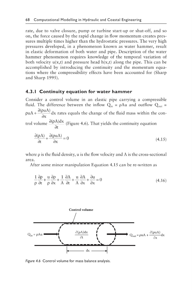
Consider a control volume in an elastic pipe carrying a compressible
fluid. The difference between the inflow Q in = ρAu and outflow Q out =
ρ
ρ
uA
uA
x
dx
+
∂
∂
(
)
rates equals the change of the fluid mass within the control volume
∂
∂
( )
ρA dx
t
(Figure 4.6). That yields the continuity equation
∂
∂
+
∂
∂
=
( )
(
)
ρ
ρ
A
t
uA
x
0
(4.15)
where ρ is the fluid density, u is the flow velocity and A is the cross-sectional
area.
After some minor manipulation Equation 4.15 can be re-written as
1
1
0
ρ
ρ
ρ
ρ
∂
∂
+
∂
∂
+
∂
∂
+
∂
∂
+
∂
∂
=
t
u
x A
A
t
u
A
A
x
u
x
(4.16)
Q out = ρuA +
dx
∂x
Q in = ρAu
dx
∂(ρA)dx
∂(ρuA)
∂t
Control volume
Figure 4.6 Control volume for mass balance analysis.
rate, due to valve closure, pump or turbine start-up or shut-off, and so
on, the force caused by the rapid change in flow momentum creates pressures multiple times higher than the hydrostatic pressures. The very high
pressures developed, in a phenomenon known as water hammer, result
in elastic deformation of both water and pipe. Description of the water
hammer phenomenon requires knowledge of the temporal variation of
both velocity u(x,t) and pressure head h(x,t) along the pipe. This can be
accomplished by introducing the continuity and the momentum equations where the compressibility effects have been accounted for (Sharp
and Sharp 1995).
4.3.1 Continuity equation for water hammer
Consider a control volume in an elastic pipe carrying a compressible
fluid. The difference between the inflow Q in = ρAu and outflow Q out =
ρ
ρ
uA
uA
x
dx
+
∂
∂
(
)
rates equals the change of the fluid mass within the control volume
∂
∂
( )
ρA dx
t
(Figure 4.6). That yields the continuity equation
∂
∂
+
∂
∂
=
( )
(
)
ρ
ρ
A
t
uA
x
0
(4.15)
where ρ is the fluid density, u is the flow velocity and A is the cross-sectional
area.
After some minor manipulation Equation 4.15 can be re-written as
1
1
0
ρ
ρ
ρ
ρ
∂
∂
+
∂
∂
+
∂
∂
+
∂
∂
+
∂
∂
=
t
u
x A
A
t
u
A
A
x
u
x
(4.16)
Q out = ρuA +
dx
∂x
Q in = ρAu
dx
∂(ρA)dx
∂(ρuA)
∂t
Control volume
Figure 4.6 Control volume for mass balance analysis.