

228
APPLICATIONS OF MULTI-DEGREE OF FREEDOM ANALYSIS
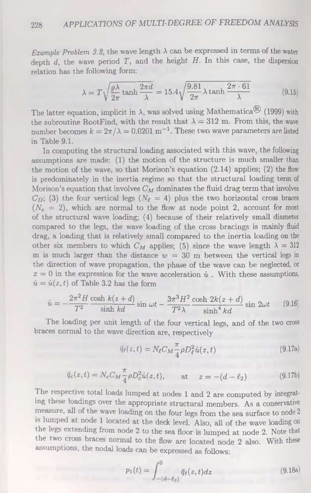
Example Problem 3.2, the wave length A can be expressed in terms of the water
depth d, the wave period T, and the height H. In this case, the dispersion
relation has the following form:
F FÔX
, 2?rd
À = T \ — tanh —— = 15.4
V 2tt
A
9.81 x
, 2rr • 61
—— A tanh —-—
2tt
A
(9.15
The latter équation, implicit in A, was solved using Mathematica® (1999) with
the subroutine RootFind, with the resuit that A — 312 m. From this, the wave
number becomes k = 2rr/A = 0.0201 m-1. These two wave parameters are listed
in Table 9.1.
In computing the structural loading associated with this wave, the following
assumptions are made: (1) the motion of the structure is much smaller than
the motion of the wave, so that Morison’s équation (2.14) applies; (2) the flow
is predominately in the inertia régime so that the structural loading term of
Morison’s équation that involves Cm dominâtes the fluid drag term that involves
Cd' , (3) the four vertical legs (Ng = 4) plus the two horizontal cross braces
(Nc = 2), which are normal to the flow at node point 2, account for most
of the structural wave loading; (4) because of their relatively small diameter
compared to the legs, the wave loading of the cross bracings is mainly fluid
drag, a loading that is relatively small compared to the inertia loading on the
other six members to which Cm applies; (5) since the wave length A = 312
m is much larger than the distance w = 30 m between the vertical legs in
the direction of wave propagation, the phase of the wave can be neglected, or
x = 0 in the expression for the wave accélération ù . With these assumptions,
û = û(z,t) of Table 3.2 has the form
u =
2ir2H cosh k(z + d)
T2
sinh kd
sin wt —
3tt3H2 cosh 2k(z + d)
T2X
sinh4 kd
sin 2u>t
(9.16:
The loading per unit length of the four vertical legs, and of the two cross
braces normal to the wave direction are, respectively
'P (z.t} = NeCM^pD2 eû(z, t)
(9.17a)
Çc(z,t) = NcCm^pD2ù(z,1),
at z=-(d-£2)
(9.17b)
The respective total loads lumped at nodes 1 and 2 are computed by integrating these loadings over the appropriate structural members. As a conservative
measure, ail of the wave loading on the four legs from the sea surface to node 2
is lumped at node 1 located at the deck level. Also, ail of the wave loading on
the legs extending from node 2 to the sea floor is lumped at node 2. Note that
the two cross braces normal to the flow are located node 2 also. With these
assumptions, the nodal loads can be expressed as follows:
Pi(t)=
qe(z,t)dz
(9.18a)
APPLICATIONS OF MULTI-DEGREE OF FREEDOM ANALYSIS
Example Problem 3.2, the wave length A can be expressed in terms of the water
depth d, the wave period T, and the height H. In this case, the dispersion
relation has the following form:
F FÔX
, 2?rd
À = T \ — tanh —— = 15.4
V 2tt
A
9.81 x
, 2rr • 61
—— A tanh —-—
2tt
A
(9.15
The latter équation, implicit in A, was solved using Mathematica® (1999) with
the subroutine RootFind, with the resuit that A — 312 m. From this, the wave
number becomes k = 2rr/A = 0.0201 m-1. These two wave parameters are listed
in Table 9.1.
In computing the structural loading associated with this wave, the following
assumptions are made: (1) the motion of the structure is much smaller than
the motion of the wave, so that Morison’s équation (2.14) applies; (2) the flow
is predominately in the inertia régime so that the structural loading term of
Morison’s équation that involves Cm dominâtes the fluid drag term that involves
Cd' , (3) the four vertical legs (Ng = 4) plus the two horizontal cross braces
(Nc = 2), which are normal to the flow at node point 2, account for most
of the structural wave loading; (4) because of their relatively small diameter
compared to the legs, the wave loading of the cross bracings is mainly fluid
drag, a loading that is relatively small compared to the inertia loading on the
other six members to which Cm applies; (5) since the wave length A = 312
m is much larger than the distance w = 30 m between the vertical legs in
the direction of wave propagation, the phase of the wave can be neglected, or
x = 0 in the expression for the wave accélération ù . With these assumptions,
û = û(z,t) of Table 3.2 has the form
u =
2ir2H cosh k(z + d)
T2
sinh kd
sin wt —
3tt3H2 cosh 2k(z + d)
T2X
sinh4 kd
sin 2u>t
(9.16:
The loading per unit length of the four vertical legs, and of the two cross
braces normal to the wave direction are, respectively
'P (z.t} = NeCM^pD2 eû(z, t)
(9.17a)
Çc(z,t) = NcCm^pD2ù(z,1),
at z=-(d-£2)
(9.17b)
The respective total loads lumped at nodes 1 and 2 are computed by integrating these loadings over the appropriate structural members. As a conservative
measure, ail of the wave loading on the four legs from the sea surface to node 2
is lumped at node 1 located at the deck level. Also, ail of the wave loading on
the legs extending from node 2 to the sea floor is lumped at node 2. Note that
the two cross braces normal to the flow are located node 2 also. With these
assumptions, the nodal loads can be expressed as follows:
Pi(t)=
qe(z,t)dz
(9.18a)