

206
MULTI-DEGREE OF FREEDOM LINEAR STRUCTURES
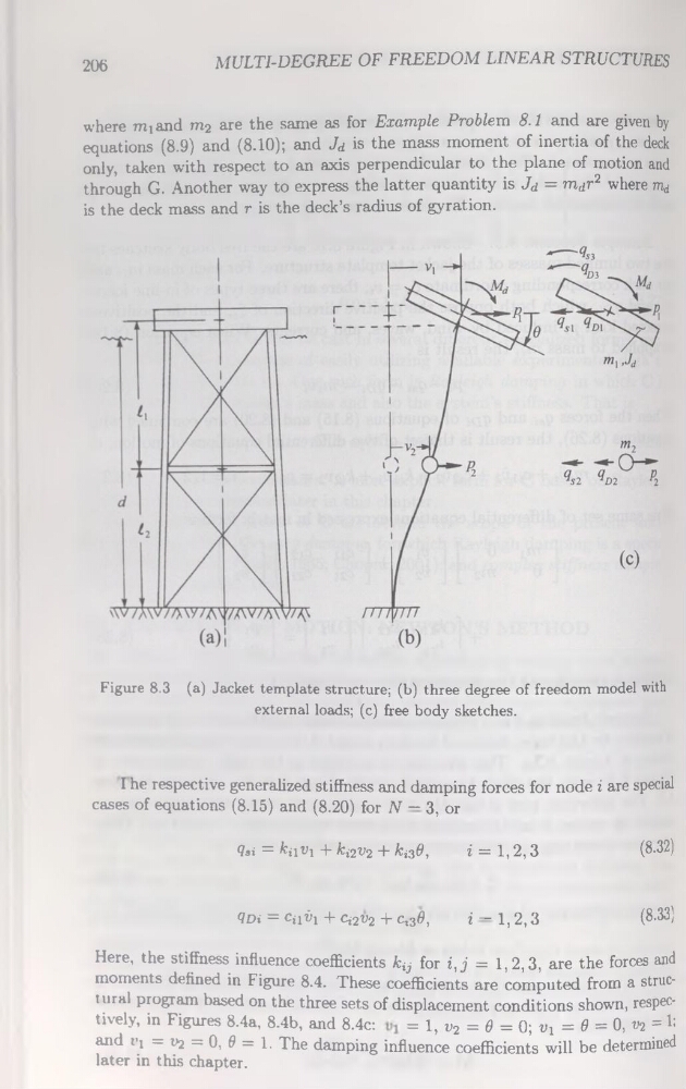
where miand m2 are the same as for Example Problem 8.1 and are given by
équations (8.9) and (8.10); and Jd is the mass moment of inertia of the deck
only, taken with respect to an axis perpendicular to the plane of motion and
through G. Another way to express the latter quantity is Jd = mdr2 where md
is the deck mass and r is the deck’s radius of gyration.
Figure 8.3 (a) Jacket template structure; (b) three degree of freedom model with
external loads; (c) free body sketches.
I he respective generalized stiffness and damping forces for node i are spécial
cases of équations (8.15) and (8.20) for N — 3, or
Çsi = kiiv-i + ki2V2 + ki3&,
i = 1,2,3
(8-32)
Qdï = Cii^i + Ci2t>2 + Ci3#,
i — 1,2,3
(8.33)
Here, the stiffness influence coefficients fcÿ for i,j = 1,2,3, are the forces and
moments defined in Figure 8.4. These coefficients are computed from a structural program based on the three sets of displacement conditions shown, respectively, in Figures 8.4a, 8.4b, and 8.4c:
= 1, v2 = 0 = Q; tq = 6 = 0, v2 = 1:
and t-! = V2 = 0, 0 = 1. The damping influence coefficients will be determined
later in this chapter.
MULTI-DEGREE OF FREEDOM LINEAR STRUCTURES
where miand m2 are the same as for Example Problem 8.1 and are given by
équations (8.9) and (8.10); and Jd is the mass moment of inertia of the deck
only, taken with respect to an axis perpendicular to the plane of motion and
through G. Another way to express the latter quantity is Jd = mdr2 where md
is the deck mass and r is the deck’s radius of gyration.
Figure 8.3 (a) Jacket template structure; (b) three degree of freedom model with
external loads; (c) free body sketches.
I he respective generalized stiffness and damping forces for node i are spécial
cases of équations (8.15) and (8.20) for N — 3, or
Çsi = kiiv-i + ki2V2 + ki3&,
i = 1,2,3
(8-32)
Qdï = Cii^i + Ci2t>2 + Ci3#,
i — 1,2,3
(8.33)
Here, the stiffness influence coefficients fcÿ for i,j = 1,2,3, are the forces and
moments defined in Figure 8.4. These coefficients are computed from a structural program based on the three sets of displacement conditions shown, respectively, in Figures 8.4a, 8.4b, and 8.4c:
= 1, v2 = 0 = Q; tq = 6 = 0, v2 = 1:
and t-! = V2 = 0, 0 = 1. The damping influence coefficients will be determined
later in this chapter.