

92
WAVE FORCES ON STRUCTURES
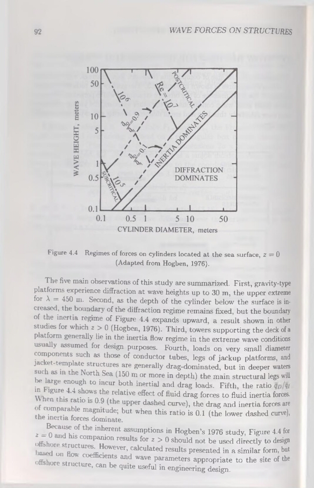
Figure 4.4 Régimes of forces on cylinders located at the sea surface, z = 0
(Adapted from Hogben, 1976).
The five main observations of this study are summarized. First, gravity-type
platforms expérience diffraction at wave heights up to 30 m, the upper extreme
for À = 450 m. Second, as the depth of the cylinder below the surface is increased, the boundary of the diffraction régime remains fixed, but the boundary
of the inertia régime of Figure 4.4 expands upward, a resuit shown in other
studies for which z > 0 (Hogben, 1976). Third, towers supporting the deck of a
platform generally lie in the inertia flow régime in the extreme wave conditions
usually assumed for design purposes. Fourth, loads on very small diameter
components such as those of conductor tubes, legs of jackup platforms, and
jacket-template structures are generally drag-dominated, but in deeper waters
such as in the North Sea (150 m or more in depth) the main structural legs will
be large enough to incur both inertial and drag loads. Fifth, the ratio
in F igure 4.4 shows the relative effect of fluid drag forces to fluid inertia forces.
When this ratio is 0.9 (the upper dashed curve), the drag and inertia forces are
<>f comparable magnitude; but when this ratio is 0.1 (the lower dashed curve),
the inertia forces dominate.
Because of the inhérent assumptions in Hogben’s 1976 study, Figure 4.4 for
z — 0 and his companion results for z > 0 should not be used directly to design
offshore structures. However, calculated results presented in a similar form, but
Iwed on flow coefficients and wave parameters appropriate to the site of the
offshore structure, can be quite useful in engineering design.
WAVE FORCES ON STRUCTURES
Figure 4.4 Régimes of forces on cylinders located at the sea surface, z = 0
(Adapted from Hogben, 1976).
The five main observations of this study are summarized. First, gravity-type
platforms expérience diffraction at wave heights up to 30 m, the upper extreme
for À = 450 m. Second, as the depth of the cylinder below the surface is increased, the boundary of the diffraction régime remains fixed, but the boundary
of the inertia régime of Figure 4.4 expands upward, a resuit shown in other
studies for which z > 0 (Hogben, 1976). Third, towers supporting the deck of a
platform generally lie in the inertia flow régime in the extreme wave conditions
usually assumed for design purposes. Fourth, loads on very small diameter
components such as those of conductor tubes, legs of jackup platforms, and
jacket-template structures are generally drag-dominated, but in deeper waters
such as in the North Sea (150 m or more in depth) the main structural legs will
be large enough to incur both inertial and drag loads. Fifth, the ratio
in F igure 4.4 shows the relative effect of fluid drag forces to fluid inertia forces.
When this ratio is 0.9 (the upper dashed curve), the drag and inertia forces are
<>f comparable magnitude; but when this ratio is 0.1 (the lower dashed curve),
the inertia forces dominate.
Because of the inhérent assumptions in Hogben’s 1976 study, Figure 4.4 for
z — 0 and his companion results for z > 0 should not be used directly to design
offshore structures. However, calculated results presented in a similar form, but
Iwed on flow coefficients and wave parameters appropriate to the site of the
offshore structure, can be quite useful in engineering design.