

388
Chapter 13 Digital Landscaping
various color ramps to show the differences in elevations, but there are several ways to make the terrain model look more realistic (and start to resemble
that image of Mount Everest from the beginning of this chapter). The first of
these techniques is called a hillshade, which models how the terrain would
look under different lighting conditions (based on the location of the Sun in
the sky). When constructing a hillshade, you can determine where the light
source (that is, the Sun) is located with respect to the terrain, thus simulating the effects of shadows being cast on the landscape by the various terrain
features.
This is done by setting two parameters for the Sun—the first of these is
the Sun altitude, a value between 0 and 90, representing the angle of the Sun
in the sky between 0 degrees (directly at the surface) and 90 degrees (directly
overhead). The second parameter is the Sun azimuth, a value between 0 and
360, representing the location of the Sun in relation to where the Sun’s rays
are coming from. The values represent a circle around the landscape, with 0
being due north, 90 being due east, 180 being due south, and 270 being due
west (the values are measured clockwise from due north). By setting values
for Sun altitude and Sun azimuth, the terrain can take on various appearances to simulate how the landscape looks under different conditions during
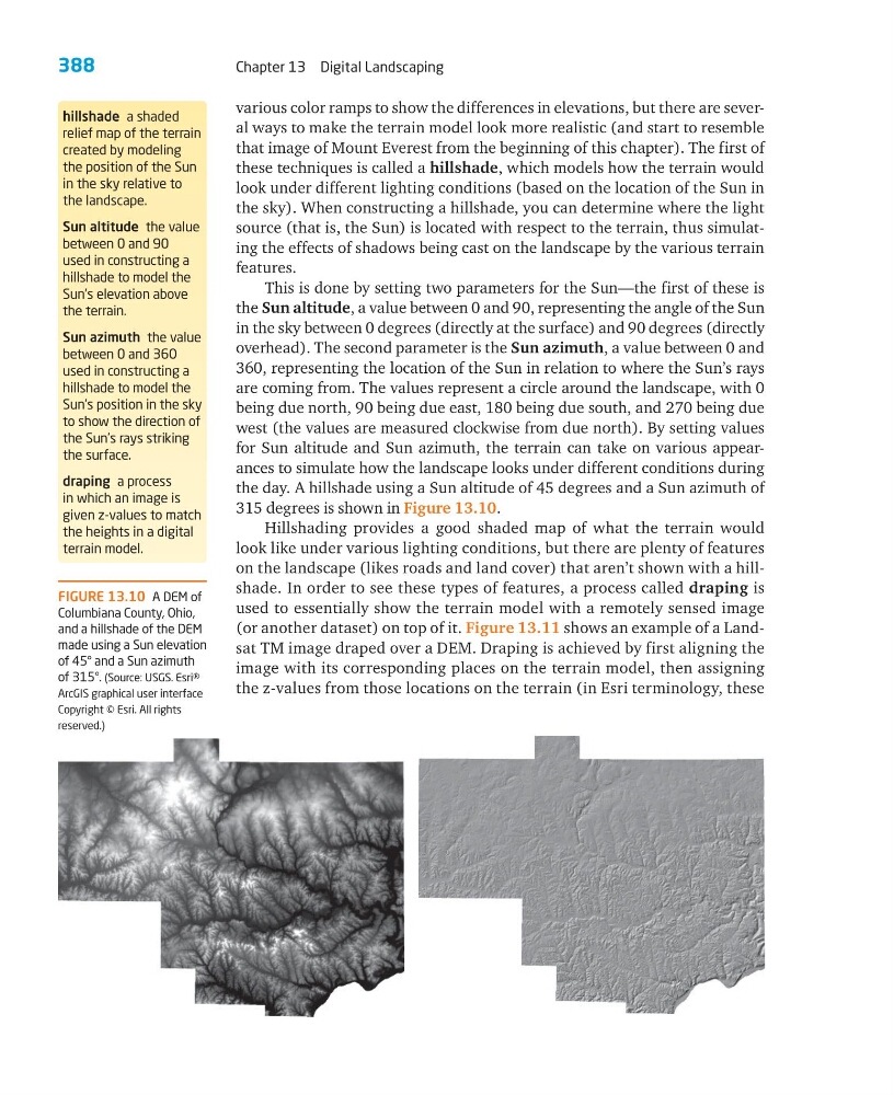
the day. A hillshade using a Sun altitude of 45 degrees and a Sun azimuth of
315 degrees is shown in Figure 13.10.
Hillshading provides a good shaded map of what the terrain would
look like under various lighting conditions, but there are plenty of features
on the landscape (likes roads and land cover) that aren’t shown with a hillshade. In order to see these types of features, a process called draping is
used to essentially show the terrain model with a remotely sensed image
(or another dataset) on top of it. Figure 13.11 shows an example of a Landsat TM image draped over a DEM. Draping is achieved by first aligning the
image with its corresponding places on the terrain model, then assigning
the z-values from those locations on the terrain (in Esri terminology, these
hillshade a shaded
relief map of the terrain
created by modeling
the position of the Sun
in the sky relative to
the landscape.
Sun altitude the value
between 0 and 90
used in constructing a
hillshade to model the
Sun’s elevation above
the terrain.
Sun azimuth the value
between 0 and 360
used in constructing a
hillshade to model the
Sun’s position in the sky
to show the direction of
the Sun’s rays striking
the surface.
draping a process
in which an image is
given z-values to match
the heights in a digital
terrain model.
FIGURE 13.10 A DEM of
Columbiana County, Ohio,
and a hillshade of the DEM
made using a Sun elevation
of 45° and a Sun azimuth
of 315°. (Source: USGS. Esri®
ArcGIS graphical user interface
Copyright © Esri. All rights
reserved.)
Chapter 13 Digital Landscaping
various color ramps to show the differences in elevations, but there are several ways to make the terrain model look more realistic (and start to resemble
that image of Mount Everest from the beginning of this chapter). The first of
these techniques is called a hillshade, which models how the terrain would
look under different lighting conditions (based on the location of the Sun in
the sky). When constructing a hillshade, you can determine where the light
source (that is, the Sun) is located with respect to the terrain, thus simulating the effects of shadows being cast on the landscape by the various terrain
features.
This is done by setting two parameters for the Sun—the first of these is
the Sun altitude, a value between 0 and 90, representing the angle of the Sun
in the sky between 0 degrees (directly at the surface) and 90 degrees (directly
overhead). The second parameter is the Sun azimuth, a value between 0 and
360, representing the location of the Sun in relation to where the Sun’s rays
are coming from. The values represent a circle around the landscape, with 0
being due north, 90 being due east, 180 being due south, and 270 being due
west (the values are measured clockwise from due north). By setting values
for Sun altitude and Sun azimuth, the terrain can take on various appearances to simulate how the landscape looks under different conditions during
the day. A hillshade using a Sun altitude of 45 degrees and a Sun azimuth of
315 degrees is shown in Figure 13.10.
Hillshading provides a good shaded map of what the terrain would
look like under various lighting conditions, but there are plenty of features
on the landscape (likes roads and land cover) that aren’t shown with a hillshade. In order to see these types of features, a process called draping is
used to essentially show the terrain model with a remotely sensed image
(or another dataset) on top of it. Figure 13.11 shows an example of a Landsat TM image draped over a DEM. Draping is achieved by first aligning the
image with its corresponding places on the terrain model, then assigning
the z-values from those locations on the terrain (in Esri terminology, these
hillshade a shaded
relief map of the terrain
created by modeling
the position of the Sun
in the sky relative to
the landscape.
Sun altitude the value
between 0 and 90
used in constructing a
hillshade to model the
Sun’s elevation above
the terrain.
Sun azimuth the value
between 0 and 360
used in constructing a
hillshade to model the
Sun’s position in the sky
to show the direction of
the Sun’s rays striking
the surface.
draping a process
in which an image is
given z-values to match
the heights in a digital
terrain model.
FIGURE 13.10 A DEM of
Columbiana County, Ohio,
and a hillshade of the DEM
made using a Sun elevation
of 45° and a Sun azimuth
of 315°. (Source: USGS. Esri®
ArcGIS graphical user interface
Copyright © Esri. All rights
reserved.)