

the point cloud is created and each cell of the grid is assigned the maximum elevation
value of all points within the cell. In a second step, the cells not assigned in the first
step are interpolated using the nearest neighbor interpolation method. It is recommended that the cell size of the grid is chosen in the order of the average point spacing
or larger, so that holes are not too large.
In some data sets, it is necessary to handle outlayers and gaps prior to the point-toraster conversion process above. Outliers are isolated points with very high or very
low elevation values which can influence the filtering process, especially because the
smoothing mechanism of the MHT decomposition will tend to diffuse such extreme
values to other cells. These extreme values may be produced by flying birds, high
antennas, and sensor faultier, among others. On the other hand, gaps are areas where
no recording of points was made. Gaps can be due to low or no energy detected by the
sensor, such as in water bodies where both high-energy absorption and specular
reflection may occur. The interpolation on gaps may cast artifacts on the final DSM,
especially in complex terrain areas. One way to deal with this problem is to use a
higher order interpolation method for gaps, such as the cubic convolution interpolation method. This should lessen the diffusive mechanism of the MHT, which tends to
propagate errors from interpolated gaps.
14.4.2 MDHT with Directional Erosion
The MDHT with directional erosion is a decomposition that adaptively processes the
transform coefficients in such a way that the inverse transform of the processed
coefficients is a surface with above-ground features removed. This process consists in
detecting ground/nonground transition cells and in applying an erosion operator to the
coefficients on detected cells. The eroded zero-order coefficient is then used for
generating the next coarser layer in the decomposition and the operations are repeated
Ground mask
generation
Point cloud
Point-to-raster
conversion
Parameters
measurement
or selection
MDHT with
directional
erosion
Eroded
DSM
Ground mask
DTM generation
Estimated
DTM
Parameters
Point labeling
Labeled
point cloud
Satisfactory
result?
No
Yes
Repeat with
estimated DTM
DSM
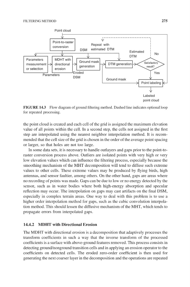
FIGURE 14.3 Flow diagram of ground filtering method. Dashed line indicates optional loop
for repeated processing.
FILTERING METHOD
275
value of all points within the cell. In a second step, the cells not assigned in the first
step are interpolated using the nearest neighbor interpolation method. It is recommended that the cell size of the grid is chosen in the order of the average point spacing
or larger, so that holes are not too large.
In some data sets, it is necessary to handle outlayers and gaps prior to the point-toraster conversion process above. Outliers are isolated points with very high or very
low elevation values which can influence the filtering process, especially because the
smoothing mechanism of the MHT decomposition will tend to diffuse such extreme
values to other cells. These extreme values may be produced by flying birds, high
antennas, and sensor faultier, among others. On the other hand, gaps are areas where
no recording of points was made. Gaps can be due to low or no energy detected by the
sensor, such as in water bodies where both high-energy absorption and specular
reflection may occur. The interpolation on gaps may cast artifacts on the final DSM,
especially in complex terrain areas. One way to deal with this problem is to use a
higher order interpolation method for gaps, such as the cubic convolution interpolation method. This should lessen the diffusive mechanism of the MHT, which tends to
propagate errors from interpolated gaps.
14.4.2 MDHT with Directional Erosion
The MDHT with directional erosion is a decomposition that adaptively processes the
transform coefficients in such a way that the inverse transform of the processed
coefficients is a surface with above-ground features removed. This process consists in
detecting ground/nonground transition cells and in applying an erosion operator to the
coefficients on detected cells. The eroded zero-order coefficient is then used for
generating the next coarser layer in the decomposition and the operations are repeated
Ground mask
generation
Point cloud
Point-to-raster
conversion
Parameters
measurement
or selection
MDHT with
directional
erosion
Eroded
DSM
Ground mask
DTM generation
Estimated
DTM
Parameters
Point labeling
Labeled
point cloud
Satisfactory
result?
No
Yes
Repeat with
estimated DTM
DSM
FIGURE 14.3 Flow diagram of ground filtering method. Dashed line indicates optional loop
for repeated processing.
FILTERING METHOD
275