

44
2.
THE MASS OF THE ELECTRON
j
_
fashion of the Helmholtz—Gaugain galvanometer coils so as to
‘
'insure uniform eld strength over the region where the vacuum
-
tube G is located. Each coil may be about 13 cm. in diameter,
2.5 cm. wide, of 60 turns of No. 16 D.Ç.C. copper
wire.
For
;
simplicity of calculation of the eld strength, the distance between
the centers of the coils should equal their radins, i.e., 2x = a.
They are connected in series aiding. The current (1 to 5 amperes)
controlled by a_rheostat and measured with the ammeter ]
.
Since the accele‘rating potential is alternating, electrons pass
through the anode only half the time, i.e., when it is positive.
They emerge with all velocities from zero to a maximum obtained
under the maximum voltage V
.
Those with greatest velocity
f
'
will be bent the least and vice versa, as indicated by the dotted
-
curves in gure 2—12. The outer edge of this beam will be found
_
to be clearly dened and should be
:
used in measuring the radins r. Since
this corresponds to electrons of maxi—
mum velocity, all voltrneter readings
'
’
(effective values) should be multi—
plied by \/Î. Obvionsly, a more
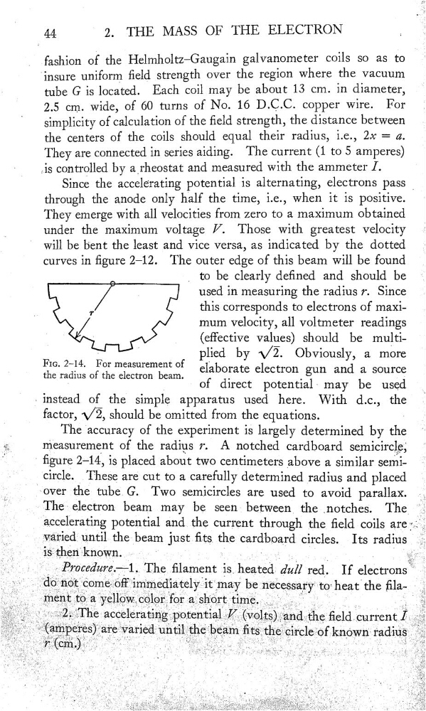
Fm” 2—.14'
For measurement °f
elaborate electron gun and a source
the rad1us of the electron beam.
.
.
'
-
of d1rect
potent1al- may be used
_
.
instead of
simple apparatus used here. With de., the
Ï
factor, \/ÏÊ, should be omitted from the equations.
The accuracy of the experiment is largely determined by the
measurement of the radins 7. A notched cardboard semicircle,‘
"
‘
gure 2—14, is placed about two centimeters above a similar seniii'
.
circle.
These are cut to a carefully determined radins and placed
_
over
the
G.
Two semicircles are used to avoid parallax.
._
The electron beam may be seen between the _notches.
potential
the current through the eld coils are
. _
until the beam just ts_ the cardboard— circles. Its radins
'
…
*
,
;
.
-
‘.
,
Ü
…
Ù__
The_.lament
du?! red- If
' ; Â d0n@tœmeoff1mmed1atelyü may
heatthe {Man
7
unttheeamtsthec1rcle of known radxus
2.
THE MASS OF THE ELECTRON
j
_
fashion of the Helmholtz—Gaugain galvanometer coils so as to
‘
'insure uniform eld strength over the region where the vacuum
-
tube G is located. Each coil may be about 13 cm. in diameter,
2.5 cm. wide, of 60 turns of No. 16 D.Ç.C. copper
wire.
For
;
simplicity of calculation of the eld strength, the distance between
the centers of the coils should equal their radins, i.e., 2x = a.
They are connected in series aiding. The current (1 to 5 amperes)
controlled by a_rheostat and measured with the ammeter ]
.
Since the accele‘rating potential is alternating, electrons pass
through the anode only half the time, i.e., when it is positive.
They emerge with all velocities from zero to a maximum obtained
under the maximum voltage V
.
Those with greatest velocity
f
'
will be bent the least and vice versa, as indicated by the dotted
-
curves in gure 2—12. The outer edge of this beam will be found
_
to be clearly dened and should be
:
used in measuring the radins r. Since
this corresponds to electrons of maxi—
mum velocity, all voltrneter readings
'
’
(effective values) should be multi—
plied by \/Î. Obvionsly, a more
Fm” 2—.14'
For measurement °f
elaborate electron gun and a source
the rad1us of the electron beam.
.
.
'
-
of d1rect
potent1al- may be used
_
.
instead of
simple apparatus used here. With de., the
Ï
factor, \/ÏÊ, should be omitted from the equations.
The accuracy of the experiment is largely determined by the
measurement of the radins 7. A notched cardboard semicircle,‘
"
‘
gure 2—14, is placed about two centimeters above a similar seniii'
.
circle.
These are cut to a carefully determined radins and placed
_
over
the
G.
Two semicircles are used to avoid parallax.
._
The electron beam may be seen between the _notches.
potential
the current through the eld coils are
. _
until the beam just ts_ the cardboard— circles. Its radins
'
…
*
,
;
.
-
‘.
,
Ü
…
Ù__
The_.lament
du?! red- If
' ; Â d0n@tœmeoff1mmed1atelyü may
heatthe {Man
7
unttheeamtsthec1rcle of known radxus