

42
2,
THE MASS OF THE ELECTRON
.
EXPERIMENT 2—2
.
MEASUREMENT
OF e/m BY A MODIFŒD LENARD METHOD
-
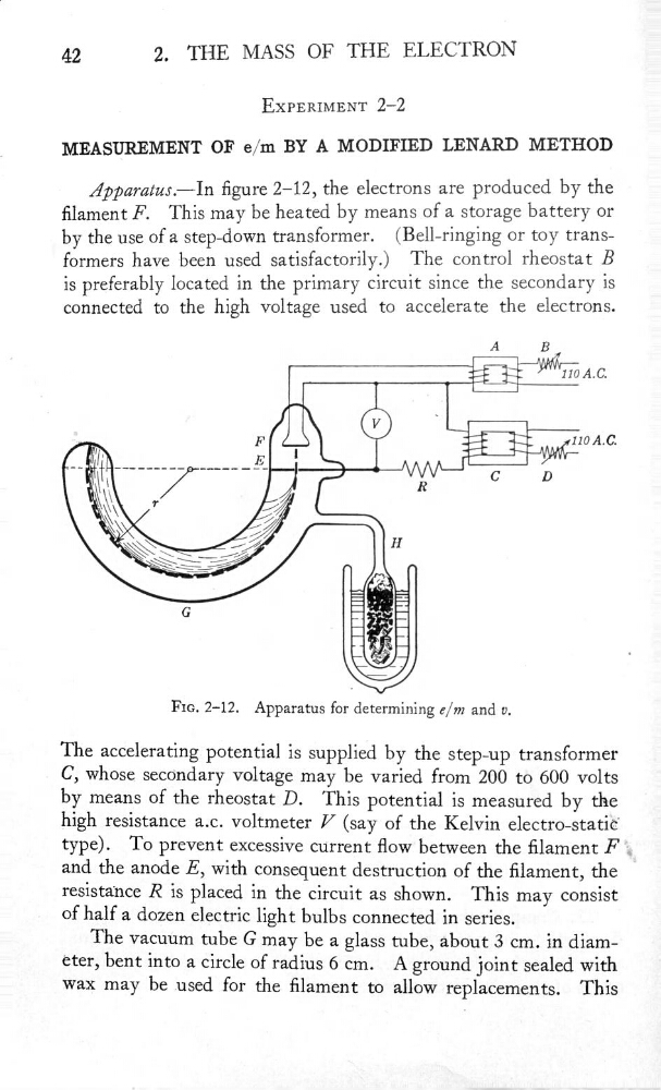
Âppamtus.—In gure 2—12, the electrons are produced by the
filament F
.
This may be heated by means of a storage battery or
-_ by the use of a step—down transformer.
(Bell—ringing or toy trans—
‘
formers have been used satisfactorily.)
The control rheostat B
is preferably located in the primary circuit since the secondary is
connected to the high voltage used to accelerate the electrons.
A
B
_
110 A.C.
,
._
V
.
‘
F
110A.C.
_E
.
"""
"”"”
C
D
.
\
R
\\
7/
/
H
\\_/
,
G
_
FIS. 2—12.
Apparatus for determining e/m and v.
The accelerating potential is supplied by the step-up transformer
.
C, whose secondary voltage may be varied from 200 to 600 volts
'
by means
of the rheostat D.
This potential is measured by the
h1gh re31stance a.c. voltmeter V (say of the Kelvin electro—static
type). T0 prevent excessive current flow between the lament F
and
the anode E, with consequent destruction of the lament, the
-
'
re31sta‘nce R is placed in the circuit as shown. This may consist
.
of half a dozen electric light bulbs connected in series.
The vacuum
tube G may be a glass tube, about 3 cm. in diam—
eter, bent into 'a circle
of radiùs 6 cm.
A ground joint sealed with
'
wax may be used for the lament to allow replacements. This
2,
THE MASS OF THE ELECTRON
.
EXPERIMENT 2—2
.
MEASUREMENT
OF e/m BY A MODIFŒD LENARD METHOD
-
Âppamtus.—In gure 2—12, the electrons are produced by the
filament F
.
This may be heated by means of a storage battery or
-_ by the use of a step—down transformer.
(Bell—ringing or toy trans—
‘
formers have been used satisfactorily.)
The control rheostat B
is preferably located in the primary circuit since the secondary is
connected to the high voltage used to accelerate the electrons.
A
B
_
110 A.C.
,
._
V
.
‘
F
110A.C.
_E
.
"""
"”"”
C
D
.
\
R
\\
7/
/
H
\\_/
,
G
_
FIS. 2—12.
Apparatus for determining e/m and v.
The accelerating potential is supplied by the step-up transformer
.
C, whose secondary voltage may be varied from 200 to 600 volts
'
by means
of the rheostat D.
This potential is measured by the
h1gh re31stance a.c. voltmeter V (say of the Kelvin electro—static
type). T0 prevent excessive current flow between the lament F
and
the anode E, with consequent destruction of the lament, the
-
'
re31sta‘nce R is placed in the circuit as shown. This may consist
.
of half a dozen electric light bulbs connected in series.
The vacuum
tube G may be a glass tube, about 3 cm. in diam—
eter, bent into 'a circle
of radiùs 6 cm.
A ground joint sealed with
'
wax may be used for the lament to allow replacements. This