

444
19.
NOTES ON HÏGH VOLTAGE TECHNIQUE
19=—3.
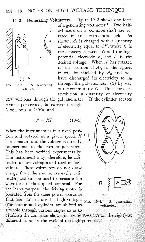
Generating Voltmeters.—Figure 19—3 shows one form
of a generating voltmeter.4 TWO half//
cylinders on a common shaft are roÂî_\A,
tated in an electro-static eld.
As
c
9
shown, .ä’1 is charged With a quantity
of electricity equal to CV
,
where C is
/
\
the capacity between Â1 and the high
«
potential electrode B, and V is the
desired voltage. When Â1 has rotated
:
to
the position of Â2, in the gure,
it Will be shielded by Â2 and Will
'"
G
have discharged its electricity to Â2
F1o.
19_3_
A
generating
through the galvanometer (G) by way
voltmeter.
of the commutator C.
Thus, for each
revolution, a quantity of electricity
ZCV Will pass through the galvanometer.
If the cylinder rotates
72 times per-second, the current through
'
G Will be ] = 20771, and
V
(19—1)
,:Î9
When the'instrument is in a xed posi‘
tion and rotated at a given speed, K
__
is a constant and the voltage is directly
(‘
j
proportional to the current generated.
{
_
This has been veried experimentally.
.
\
The instrument may, therefore, be cali.,
‘
brated at low voltages and used at high
-
.
values. These voltmeters do not draw
.
energy from the source, are easily cali.
:
be used to measure the
.
Waveform of the applied potential. For
_
R_ ,.-læ .
'
the—latter purpose, the driving— motor is
;
'
"
;
“operated fromthe same powersource as
,
"
,
that
Produœ the high
‘
”A “gael—atii‘g
The In'0tOf 'a‘nd‘“cylinder are shifted aS '
'
‘
Ï
.,
aftwhole through Various 'angl‘es's‘oàs t0”=
'
the condition …sh“oWn gin
19—3
different times in _the_cÿCl‘e of th€ h1ghpotent1al 1…_
19.
NOTES ON HÏGH VOLTAGE TECHNIQUE
19=—3.
Generating Voltmeters.—Figure 19—3 shows one form
of a generating voltmeter.4 TWO half//
cylinders on a common shaft are roÂî_\A,
tated in an electro-static eld.
As
c
9
shown, .ä’1 is charged With a quantity
of electricity equal to CV
,
where C is
/
\
the capacity between Â1 and the high
«
potential electrode B, and V is the
desired voltage. When Â1 has rotated
:
to
the position of Â2, in the gure,
it Will be shielded by Â2 and Will
'"
G
have discharged its electricity to Â2
F1o.
19_3_
A
generating
through the galvanometer (G) by way
voltmeter.
of the commutator C.
Thus, for each
revolution, a quantity of electricity
ZCV Will pass through the galvanometer.
If the cylinder rotates
72 times per-second, the current through
'
G Will be ] = 20771, and
V
(19—1)
,:Î9
When the'instrument is in a xed posi‘
tion and rotated at a given speed, K
__
is a constant and the voltage is directly
(‘
j
proportional to the current generated.
{
_
This has been veried experimentally.
.
\
The instrument may, therefore, be cali.,
‘
brated at low voltages and used at high
-
.
values. These voltmeters do not draw
.
energy from the source, are easily cali.
:
be used to measure the
.
Waveform of the applied potential. For
_
R_ ,.-læ .
'
the—latter purpose, the driving— motor is
;
'
"
;
“operated fromthe same powersource as
,
"
,
that
Produœ the high
‘
”A “gael—atii‘g
The In'0tOf 'a‘nd‘“cylinder are shifted aS '
'
‘
Ï
.,
aftwhole through Various 'angl‘es's‘oàs t0”=
'
the condition …sh“oWn gin
19—3
different times in _the_cÿCl‘e of th€ h1ghpotent1al 1…_