

18—9.
COUNTER TUBE CIRCUITS
425
on
the meter (M ) or by the operation of a relay or counter mechan_
.
_
1sm.
In practice, in this and the following circuits, the vacuum
tube is of thescreen grid or pentode type in order to prevent feed '
back.
If desrred,
a second amplier tube may be added to invert
the phase; 1._e.,
drive the second grid positive and cause an increase, '
rather than a decrease, in the output plate current. The second
C
.
=
.
'
==
.
-
N‘ +
—.
_
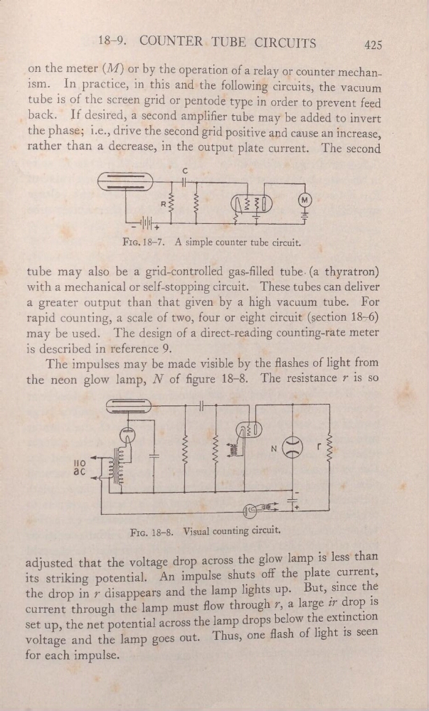
FIG.18—7.
A simple counter tube circuit.
tube may also be a grid—controlled gas-lled tube. (a thyra'tron)
With a mechanical or self-stopping circuit. These tubes can deliver
a greater output than that given by a high vacuum tube. For
rapid counting, a scale of two, four or eight circuit? (section 1876)
may be used.
The design of a direct-reading counting-r—ate meter
is described in reference _9.
_
The impulses may be made visible by the ashes of light from
the neon glow lamp, N of gure 18—8. The resistance r is so
“
'
*
?” ea
'
'a”ê Ê'l
.
_
FIG. 18—8.
Visual
circuit.
,
.
adjusted that the
across the glow lamp is'less than
its striking potential.
An impulse
the plate purrent,_
_
'
the drop in 7 disappears and the lamp llghtS UP' But, smce the
current through the lamp
mUSË HOW
a, large
Ëlr°P
13
.
set up,
the net potential across the lamp drops below the extinct10n _
voltage and the lamp goes
out.
"I‘hus,
of light rs
seen
foreaChimpulse.
'
Q,
-
’—
"
COUNTER TUBE CIRCUITS
425
on
the meter (M ) or by the operation of a relay or counter mechan_
.
_
1sm.
In practice, in this and the following circuits, the vacuum
tube is of thescreen grid or pentode type in order to prevent feed '
back.
If desrred,
a second amplier tube may be added to invert
the phase; 1._e.,
drive the second grid positive and cause an increase, '
rather than a decrease, in the output plate current. The second
C
.
=
.
'
==
.
-
N‘ +
—.
_
FIG.18—7.
A simple counter tube circuit.
tube may also be a grid—controlled gas-lled tube. (a thyra'tron)
With a mechanical or self-stopping circuit. These tubes can deliver
a greater output than that given by a high vacuum tube. For
rapid counting, a scale of two, four or eight circuit? (section 1876)
may be used.
The design of a direct-reading counting-r—ate meter
is described in reference _9.
_
The impulses may be made visible by the ashes of light from
the neon glow lamp, N of gure 18—8. The resistance r is so
“
'
*
?” ea
'
'a”ê Ê'l
.
_
FIG. 18—8.
Visual
circuit.
,
.
adjusted that the
across the glow lamp is'less than
its striking potential.
An impulse
the plate purrent,_
_
'
the drop in 7 disappears and the lamp llghtS UP' But, smce the
current through the lamp
mUSË HOW
a, large
Ëlr°P
13
.
set up,
the net potential across the lamp drops below the extinct10n _
voltage and the lamp goes
out.
"I‘hus,
of light rs
seen
foreaChimpulse.
'
Q,
-
’—
"