

304
13.
THE ACCELERATION OF IONS
;
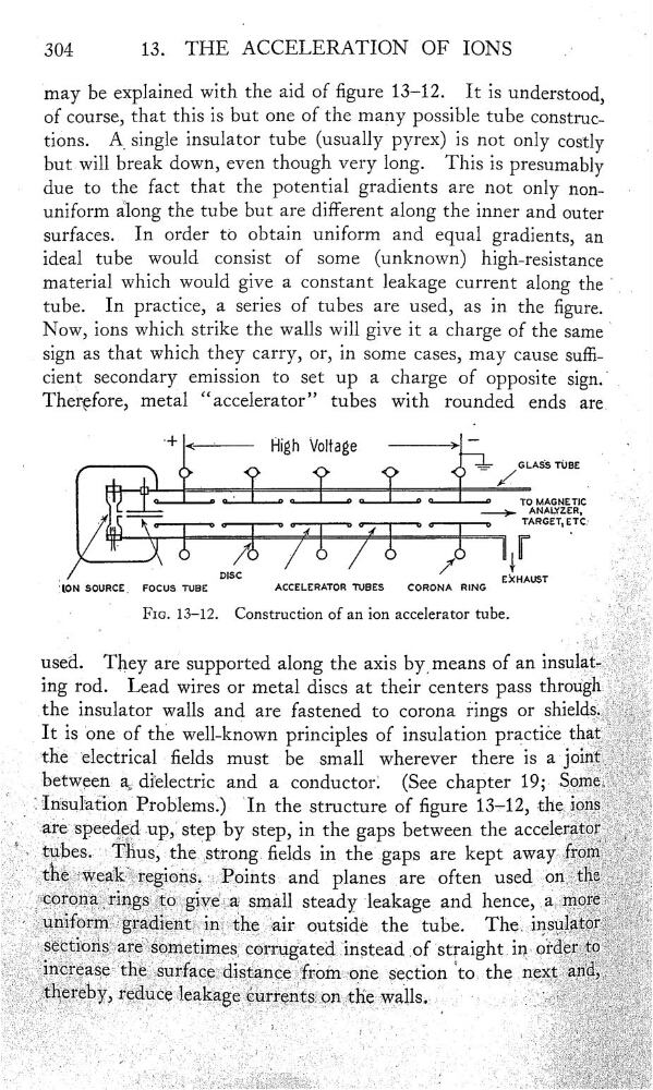
may be explained with the aid of gure 13—12. It is understood,
of course, that this is but one of the many possible tube construc—
tiOns.
A_ single insulator tube (usually pyrex) is not only costly
butwill break down, even though very long. This is presumably
due to the fact that the potential gradients are not only nonuniform along the tube but are different along the inner and outer
surfaces.
In order to obtain uniform and equal gradients, an
ideal tube would consist of some (unknown) high—resistance
material which would give a constant leakage current along the
tube.
In practice, a series of tubes are used, as in the gure.
Now, ions which strike the walls will give it a charge of the same
sign as that which they carry, or, in some cases, may cause sui‘
cient secondary emission to set up a charge of opposite
.
Therçfore, metal “accelerator” tubes with rounded ends are
"+
<——‘——
High Voltage
——>
"
,
‘
,
.
.
.
_.
_ .
___
GLASS TUBE
_
_
_
_
_
_
_
_
,
TARGET,ETCJ
‘
o
/o
-
o
.
lÎ
Ï
ËlON sounce_
FOCUS TUBE
DISC
ACCELERATOR TUBES
CORONA
RING
EXHAUST
FIG. 13—12.
Construction of an ion accelerator tube.
used.
They are supported along the axis bymeans of an insulat—
ing rod. Lead wires or metal discs at their centers pass through
'
the insulator walls and are fastened to corona rings or
It is 'one of the well—known principles of insulation practice that
,
_
«“the electrical elds must be small wherever there is a J01nt
_
…
betWeen
dielectric and a conductorl
(See chapter 19; Some
the structure of gure 13—12, thelonS
afespeeded
by step, in the gaps
between the accelerat0r
ThUS,
elds in the' gaps are kept awayff0m‘
theweakregions .}P_Ïo‘ihts and planes are often usedonthe
section
the nextand
therebyreduœ1@akagecumntsonthewalls
-
,
13.
THE ACCELERATION OF IONS
;
may be explained with the aid of gure 13—12. It is understood,
of course, that this is but one of the many possible tube construc—
tiOns.
A_ single insulator tube (usually pyrex) is not only costly
butwill break down, even though very long. This is presumably
due to the fact that the potential gradients are not only nonuniform along the tube but are different along the inner and outer
surfaces.
In order to obtain uniform and equal gradients, an
ideal tube would consist of some (unknown) high—resistance
material which would give a constant leakage current along the
tube.
In practice, a series of tubes are used, as in the gure.
Now, ions which strike the walls will give it a charge of the same
sign as that which they carry, or, in some cases, may cause sui‘
cient secondary emission to set up a charge of opposite
.
Therçfore, metal “accelerator” tubes with rounded ends are
"+
<——‘——
High Voltage
——>
"
,
‘
,
.
.
.
_.
_ .
___
GLASS TUBE
_
_
_
_
_
_
_
_
,
TARGET,ETCJ
‘
o
/o
-
o
.
lÎ
Ï
ËlON sounce_
FOCUS TUBE
DISC
ACCELERATOR TUBES
CORONA
RING
EXHAUST
FIG. 13—12.
Construction of an ion accelerator tube.
used.
They are supported along the axis bymeans of an insulat—
ing rod. Lead wires or metal discs at their centers pass through
'
the insulator walls and are fastened to corona rings or
It is 'one of the well—known principles of insulation practice that
,
_
«“the electrical elds must be small wherever there is a J01nt
_
…
betWeen
dielectric and a conductorl
(See chapter 19; Some
the structure of gure 13—12, thelonS
afespeeded
by step, in the gaps
between the accelerat0r
ThUS,
elds in the' gaps are kept awayff0m‘
theweakregions .}P_Ïo‘ihts and planes are often usedonthe
section
the nextand
therebyreduœ1@akagecumntsonthewalls
-
,