

6—12.
ELECTRON OPTICS
î33
be — 40 centimeters, the image would be virtual and the electrons would diverge as they passed the hole.
Combinations of two or more diaphragm lenses of the type
shown in gure 6—19 (&) have been used in electron-microscopes to
produce magnied, inverted, real images of the surface of the la—
ment, permitting detailed studies of the emissive properties of
various cathodes.
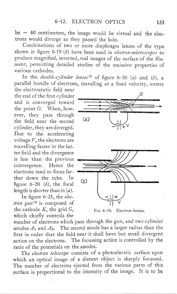
In the double—cyiinder [87756513 of gure 6—20 (52) and (&), a
parallel bundle of electrons, travelling at a xed velocity, enters
the electrostatic eld near
the end of the rst cylinder
……
_
_
0
and is converged toward
ever,
they pass through
'
.….
.,
the eld near the second
(a)
cylinder, they are diverged.
_
l' "'V
Due to
the
accelerating
voltage V
,
the electrons are
_
travelling faster in the latter eld and the divergence
'
is less than the previous
.…\\/Jl
convergence.
Hence the
===—:
.
—_>
electrons tend to focus far"
ther down the tube.
In
(b)
\
gure 6—20 (à), the focal
"
length is shorter than in (a).
In gure 6—21, the elec.
—
l'
+
‘
iron gun“ is composed of
V
the cath0de K: the grid GJ
FIG. 6—20.
Electron lenses.
Which chiey controls the
.
number of electrons which pass through the gun, and two cylinder
anodes A’ 1 and Â2.
The second anode has a larger radins than the
rst in order that the eld near it shall have but small divergent
action on the electrons.
The focussing action is controlled by the
ratio of the potentials on the anodes.
The electron z‘elescope consists of a photoelectric surface upon
Which an optical image of a distant object is sharply focussed.
The number of electr0ns ejected from the various parts of this
surface is proportional to the intensity of the image. It is to be
ELECTRON OPTICS
î33
be — 40 centimeters, the image would be virtual and the electrons would diverge as they passed the hole.
Combinations of two or more diaphragm lenses of the type
shown in gure 6—19 (&) have been used in electron-microscopes to
produce magnied, inverted, real images of the surface of the la—
ment, permitting detailed studies of the emissive properties of
various cathodes.
In the double—cyiinder [87756513 of gure 6—20 (52) and (&), a
parallel bundle of electrons, travelling at a xed velocity, enters
the electrostatic eld near
the end of the rst cylinder
……
_
_
0
and is converged toward
ever,
they pass through
'
.….
.,
the eld near the second
(a)
cylinder, they are diverged.
_
l' "'V
Due to
the
accelerating
voltage V
,
the electrons are
_
travelling faster in the latter eld and the divergence
'
is less than the previous
.…\\/Jl
convergence.
Hence the
===—:
.
—_>
electrons tend to focus far"
ther down the tube.
In
(b)
\
gure 6—20 (à), the focal
"
length is shorter than in (a).
In gure 6—21, the elec.
—
l'
+
‘
iron gun“ is composed of
V
the cath0de K: the grid GJ
FIG. 6—20.
Electron lenses.
Which chiey controls the
.
number of electrons which pass through the gun, and two cylinder
anodes A’ 1 and Â2.
The second anode has a larger radins than the
rst in order that the eld near it shall have but small divergent
action on the electrons.
The focussing action is controlled by the
ratio of the potentials on the anodes.
The electron z‘elescope consists of a photoelectric surface upon
Which an optical image of a distant object is sharply focussed.
The number of electr0ns ejected from the various parts of this
surface is proportional to the intensity of the image. It is to be