

54
2: Raghuveer M. Rao, Manoj K. Arora
in that band. The lowest gray value in each band provides an estimate of the
contribution to each pixel's gray value in that band from neighboring pixels.
In the visible region, atmospheric scattering injects extraneous radiation at
higher frequencies. Consequently the bulk correction just described tends to
reduce the blue component.
The radiometric distortion may also occur due to the image capture system
itself. If the response of the detector is a nonlinear function of the input
radiance, it results in nonlinear distortion. Another source of instrumentation
error in multi-detector cameras is mismatch of detector characteristics, that is,
each detector may have a slightly different transfer characteristic (even iflinear)
and offset. Offset refers to the fact that each detector outputs a different dark
current, which is the current from a radiation-sensing device even when there
is no radiation impinging on it. Yet another common source of contribution
of instruments to radiometric distortion is sensor noise, which shows up as
random deviations from the true intensity values.
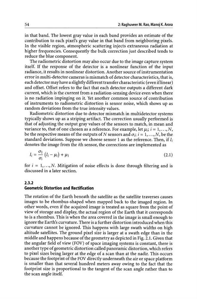
Radiometric distortion due to detector mismatch in multidetector systems
typically shows up as a striping artifact. The correction usually performed is
that of adjusting the output gray values of the sensors to match, in mean and
variance to, that of one chosen as a reference. For example, let Pi; i = 1, ... , N,
be the respective means of the outputs of N sensors and 0i; i = 1, ... , N, be the
standard deviations. Suppose we choose sensor 1 as the reference. Then, if Ii
denotes the image from the ith sensor, the corrections are implemented as
(2.1)
for i = 1, ... , N. Mitigation of noise effects is done through filtering and is
discussed in a later section.
2.3.2
Geometric Distortion and Rectification
The rotation of the Earth beneath the satellite as the satellite traverses causes
images to be rhombus-shaped when mapped back to the imaged region. In
other words, even if the acquired image is treated as square from the point of
view of storage and display, the actual region of the Earth that it corresponds
to is a rhombus. This is when the area covered in the image is small enough to
ignore the Earth's curvature. There is a further distortion introduced when this
curvature cannot be ignored. This happens with large swath widths on high
altitude satellites. The ground pixel size is larger at a swath edge than in the
middle and happens because of the geometry as depicted in Fig. 2.1. Given that
the angular field of view (FOV) of space imaging systems is constant, there is
another type of geometric distortion called panoramic distortion, which refers
to pixel sizes being larger at the edge of a scan than at the nadir. This occurs
because the footprint of the FOV directly underneath the air or space platform
is smaller than that several hundred meters away owing to the fact that the
footprint size is proportional to the tangent of the scan angle rather than to
the scan angle itself.
2: Raghuveer M. Rao, Manoj K. Arora
in that band. The lowest gray value in each band provides an estimate of the
contribution to each pixel's gray value in that band from neighboring pixels.
In the visible region, atmospheric scattering injects extraneous radiation at
higher frequencies. Consequently the bulk correction just described tends to
reduce the blue component.
The radiometric distortion may also occur due to the image capture system
itself. If the response of the detector is a nonlinear function of the input
radiance, it results in nonlinear distortion. Another source of instrumentation
error in multi-detector cameras is mismatch of detector characteristics, that is,
each detector may have a slightly different transfer characteristic (even iflinear)
and offset. Offset refers to the fact that each detector outputs a different dark
current, which is the current from a radiation-sensing device even when there
is no radiation impinging on it. Yet another common source of contribution
of instruments to radiometric distortion is sensor noise, which shows up as
random deviations from the true intensity values.
Radiometric distortion due to detector mismatch in multidetector systems
typically shows up as a striping artifact. The correction usually performed is
that of adjusting the output gray values of the sensors to match, in mean and
variance to, that of one chosen as a reference. For example, let Pi; i = 1, ... , N,
be the respective means of the outputs of N sensors and 0i; i = 1, ... , N, be the
standard deviations. Suppose we choose sensor 1 as the reference. Then, if Ii
denotes the image from the ith sensor, the corrections are implemented as
(2.1)
for i = 1, ... , N. Mitigation of noise effects is done through filtering and is
discussed in a later section.
2.3.2
Geometric Distortion and Rectification
The rotation of the Earth beneath the satellite as the satellite traverses causes
images to be rhombus-shaped when mapped back to the imaged region. In
other words, even if the acquired image is treated as square from the point of
view of storage and display, the actual region of the Earth that it corresponds
to is a rhombus. This is when the area covered in the image is small enough to
ignore the Earth's curvature. There is a further distortion introduced when this
curvature cannot be ignored. This happens with large swath widths on high
altitude satellites. The ground pixel size is larger at a swath edge than in the
middle and happens because of the geometry as depicted in Fig. 2.1. Given that
the angular field of view (FOV) of space imaging systems is constant, there is
another type of geometric distortion called panoramic distortion, which refers
to pixel sizes being larger at the edge of a scan than at the nadir. This occurs
because the footprint of the FOV directly underneath the air or space platform
is smaller than that several hundred meters away owing to the fact that the
footprint size is proportional to the tangent of the scan angle rather than to
the scan angle itself.