

All input and output files in WASI are in text format (ASCII), making it easy to
adapt calculations to regional circumstances by replacing some default input spectra
and changing material-specific constants. A well-designed graphical user interface
allows intuitive operation. An example of the interface is shown in Figure 1.
Alternatively, WASI can be operated in a background mode where all actions are
controlled by an input file. In this mode other programs can utilize WASI as a slave to
generate or analyze data according to their demands. This input file, WASI.INI, is also
used to initialize and document all program settings. It is automatically read during
program start up, and a copy with the actual settings is automatically stored in the
relevant directory whenever outputs from calculations are saved.
An overall description of WASI was given in Gege (2004). This chapter focuses on
data analysis for inverse modeling of spectral measurements. Implemented algorithms,
including newly developed models for shallow water, are summarized. Problems
associated with inverse modeling, and solutions offered for WASI, are discussed.
Finally, some examples of how to apply the program effectively are presented.
2. Models
2.1 ABSORPTION
2.1.1 Water constituents
Absorption of a mixture of water constituents is the sum of the components’
absorption coefficients:
,
)
(
a
Y
)
(
a
X
)
(
a
C
)
(
a
*
Y
5
0
i
*
X
*
i
i
WC
λ
⋅
+
λ
⋅
+
λ
⋅
=
λ
¦
=
(1)
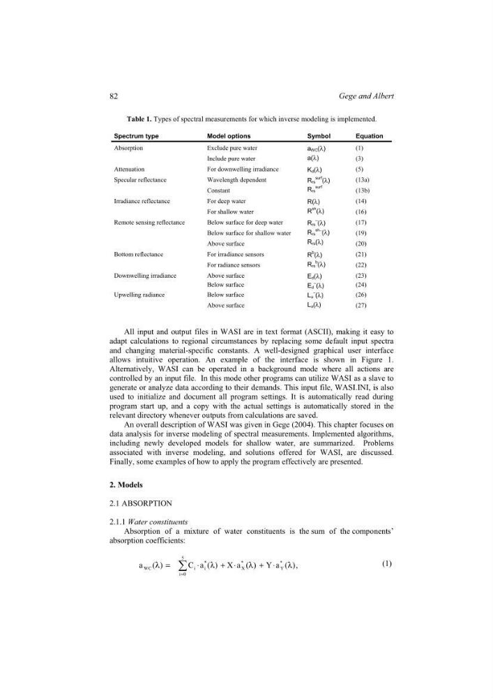
Table 1. Types of spectral measurements for which inverse modeling is implemented.
Spectrum type
Model options
Symbol
Equation
Absorption
Exclude pure water
Include pure water
a WC (λ)
a(λ)
(1)
(3)
Attenuation
For downwelling irradiance
K d (λ)
(5)
Specular reflectance
Wavelength dependent
Constant
R rs
surf (λ)
Rrs
surf
(13a)
(13b)
Irradiance reflectance
For deep water
For shallow water
R(λ)
R
sh (λ)
(14)
(16)
Remote sensing reflectance
Below surface for deep water
Below surface for shallow water
Above surface
Rrs
–
(λ)
R rs
sh−
(λ)
R rs (λ)
(17)
(19)
(20)
Bottom reflectance
For irradiance sensors
For radiance sensors
R
b (λ)
R rs
b
(λ)
(21)
(22)
Downwelling irradiance
Above surface
Below surface
Ed(λ)
E d
– (λ)
(23)
(24)
Upwelling radiance
Below surface
Above surface
Lu
– (λ)
L u (λ)
(26)
(27)
82
Gege and Albert
adapt calculations to regional circumstances by replacing some default input spectra
and changing material-specific constants. A well-designed graphical user interface
allows intuitive operation. An example of the interface is shown in Figure 1.
Alternatively, WASI can be operated in a background mode where all actions are
controlled by an input file. In this mode other programs can utilize WASI as a slave to
generate or analyze data according to their demands. This input file, WASI.INI, is also
used to initialize and document all program settings. It is automatically read during
program start up, and a copy with the actual settings is automatically stored in the
relevant directory whenever outputs from calculations are saved.
An overall description of WASI was given in Gege (2004). This chapter focuses on
data analysis for inverse modeling of spectral measurements. Implemented algorithms,
including newly developed models for shallow water, are summarized. Problems
associated with inverse modeling, and solutions offered for WASI, are discussed.
Finally, some examples of how to apply the program effectively are presented.
2. Models
2.1 ABSORPTION
2.1.1 Water constituents
Absorption of a mixture of water constituents is the sum of the components’
absorption coefficients:
,
)
(
a
Y
)
(
a
X
)
(
a
C
)
(
a
*
Y
5
0
i
*
X
*
i
i
WC
λ
⋅
+
λ
⋅
+
λ
⋅
=
λ
¦
=
(1)
Table 1. Types of spectral measurements for which inverse modeling is implemented.
Spectrum type
Model options
Symbol
Equation
Absorption
Exclude pure water
Include pure water
a WC (λ)
a(λ)
(1)
(3)
Attenuation
For downwelling irradiance
K d (λ)
(5)
Specular reflectance
Wavelength dependent
Constant
R rs
surf (λ)
Rrs
surf
(13a)
(13b)
Irradiance reflectance
For deep water
For shallow water
R(λ)
R
sh (λ)
(14)
(16)
Remote sensing reflectance
Below surface for deep water
Below surface for shallow water
Above surface
Rrs
–
(λ)
R rs
sh−
(λ)
R rs (λ)
(17)
(19)
(20)
Bottom reflectance
For irradiance sensors
For radiance sensors
R
b (λ)
R rs
b
(λ)
(21)
(22)
Downwelling irradiance
Above surface
Below surface
Ed(λ)
E d
– (λ)
(23)
(24)
Upwelling radiance
Below surface
Above surface
Lu
– (λ)
L u (λ)
(26)
(27)
82
Gege and Albert