

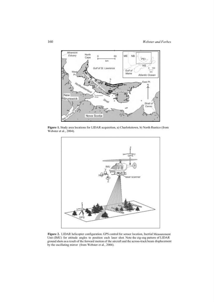
Figure 1. Study area locations for LIDAR acquisition, a) Charlottetown, b) North Rustico (from
Webster et al., 2004).
Figure 2. LIDAR helicopter configuration. GPS control for sensor location, Inertial Measurement
Unit (IMU) for attitude angles to position each laser shot. Note the zig-zag pattern of LIDAR
ground shots as a result of the forward motion of the aircraft and the across-track beam displacement
by the oscillating mirror (from Webster et al., 2004).
160
Webster and Forbes
Webster et al., 2004).
Figure 2. LIDAR helicopter configuration. GPS control for sensor location, Inertial Measurement
Unit (IMU) for attitude angles to position each laser shot. Note the zig-zag pattern of LIDAR
ground shots as a result of the forward motion of the aircraft and the across-track beam displacement
by the oscillating mirror (from Webster et al., 2004).
160
Webster and Forbes