

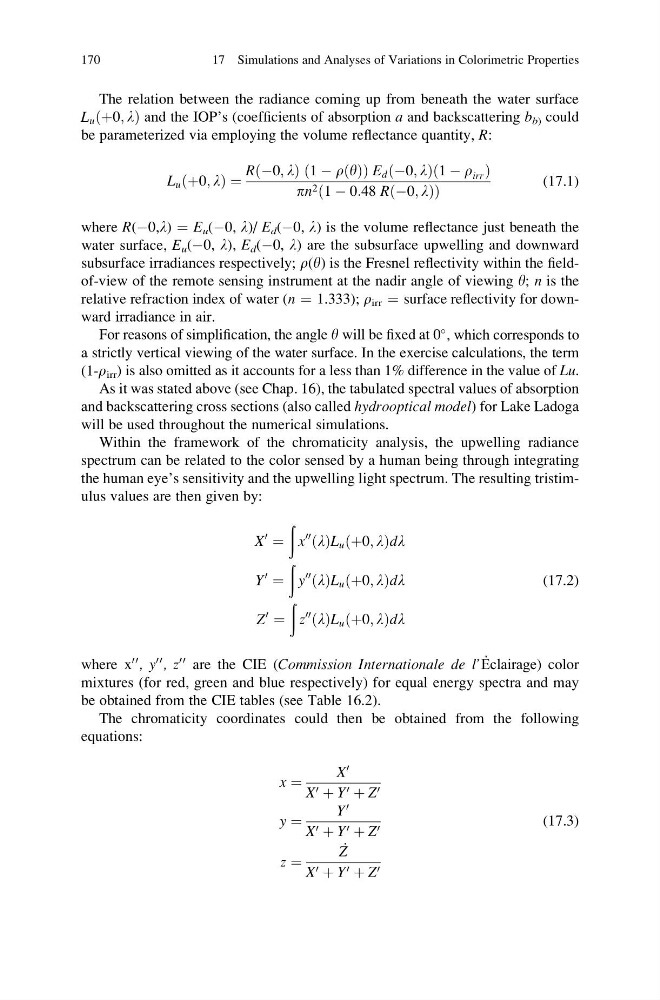
The relation between the radiance coming up from beneath the water surface
L u ðþ0; lÞ and the IOP’s (coefficients of absorption a and backscattering b b) could
be parameterized via employing the volume reflectance quantity, R:
L u þ0; l
ð
Þ¼
R À0; l
ð
Þ 1 À r y
ð Þ
ð
ÞE d À0; l
ð
Þð1 À r irr Þ
pn 2 1 À 0:48 R À0; l
ð
Þ
ð
Þ
(17.1)
where R(À0,l) ¼ E u (À0, l)/ E d (À0, l) is the volume reflectance just beneath the
water surface, E u (À0, l), E d (À0, l) are the subsurface upwelling and downward
subsurface irradiances respectively; r(y) is the Fresnel reflectivity within the fieldof-view of the remote sensing instrument at the nadir angle of viewing y; n is the
relative refraction index of water (n ¼ 1.333); r irr ¼ surface reflectivity for downward irradiance in air.
For reasons of simplification, the angle y will be fixed at 0
, which corresponds to
a strictly vertical viewing of the water surface. In the exercise calculations, the term
(1-r irr ) is also omitted as it accounts for a less than 1% difference in the value of Lu.
As it was stated above (see Chap. 16), the tabulated spectral values of absorption
and backscattering cross sections (also called hydrooptical model) for Lake Ladoga
will be used throughout the numerical simulations.
Within the framework of the chromaticity analysis, the upwelling radiance
spectrum can be related to the color sensed by a human being through integrating
the human eye’s sensitivity and the upwelling light spectrum. The resulting tristimulus values are then given by:
X
0
¼
ð
x
00
ðlÞL u ðþ0; lÞdl
Y
0
¼
ð
y
00
ðlÞL u ðþ0; lÞdl
Z
0
¼
ð
z
00
ðlÞL u ðþ0; lÞdl
(17.2)
where x
00 , y
00 , z
00 are the CIE (Commission Internationale de l’Ẻclairage) color
mixtures (for red, green and blue respectively) for equal energy spectra and may
be obtained from the CIE tables (see Table 16.2).
The chromaticity coordinates could then be obtained from the following
equations:
x ¼
X
0
X 0 þ Y 0 þ Z 0
y ¼
Y
0
X 0 þ Y 0 þ Z 0
z ¼
_
Z
X 0 þ Y 0 þ Z 0
(17.3)
170
17 Simulations and Analyses of Variations in Colorimetric Properties
L u ðþ0; lÞ and the IOP’s (coefficients of absorption a and backscattering b b) could
be parameterized via employing the volume reflectance quantity, R:
L u þ0; l
ð
Þ¼
R À0; l
ð
Þ 1 À r y
ð Þ
ð
ÞE d À0; l
ð
Þð1 À r irr Þ
pn 2 1 À 0:48 R À0; l
ð
Þ
ð
Þ
(17.1)
where R(À0,l) ¼ E u (À0, l)/ E d (À0, l) is the volume reflectance just beneath the
water surface, E u (À0, l), E d (À0, l) are the subsurface upwelling and downward
subsurface irradiances respectively; r(y) is the Fresnel reflectivity within the fieldof-view of the remote sensing instrument at the nadir angle of viewing y; n is the
relative refraction index of water (n ¼ 1.333); r irr ¼ surface reflectivity for downward irradiance in air.
For reasons of simplification, the angle y will be fixed at 0
, which corresponds to
a strictly vertical viewing of the water surface. In the exercise calculations, the term
(1-r irr ) is also omitted as it accounts for a less than 1% difference in the value of Lu.
As it was stated above (see Chap. 16), the tabulated spectral values of absorption
and backscattering cross sections (also called hydrooptical model) for Lake Ladoga
will be used throughout the numerical simulations.
Within the framework of the chromaticity analysis, the upwelling radiance
spectrum can be related to the color sensed by a human being through integrating
the human eye’s sensitivity and the upwelling light spectrum. The resulting tristimulus values are then given by:
X
0
¼
ð
x
00
ðlÞL u ðþ0; lÞdl
Y
0
¼
ð
y
00
ðlÞL u ðþ0; lÞdl
Z
0
¼
ð
z
00
ðlÞL u ðþ0; lÞdl
(17.2)
where x
00 , y
00 , z
00 are the CIE (Commission Internationale de l’Ẻclairage) color
mixtures (for red, green and blue respectively) for equal energy spectra and may
be obtained from the CIE tables (see Table 16.2).
The chromaticity coordinates could then be obtained from the following
equations:
x ¼
X
0
X 0 þ Y 0 þ Z 0
y ¼
Y
0
X 0 þ Y 0 þ Z 0
z ¼
_
Z
X 0 þ Y 0 þ Z 0
(17.3)
170
17 Simulations and Analyses of Variations in Colorimetric Properties