

92
Marian de Vries and Peter van Oosterom
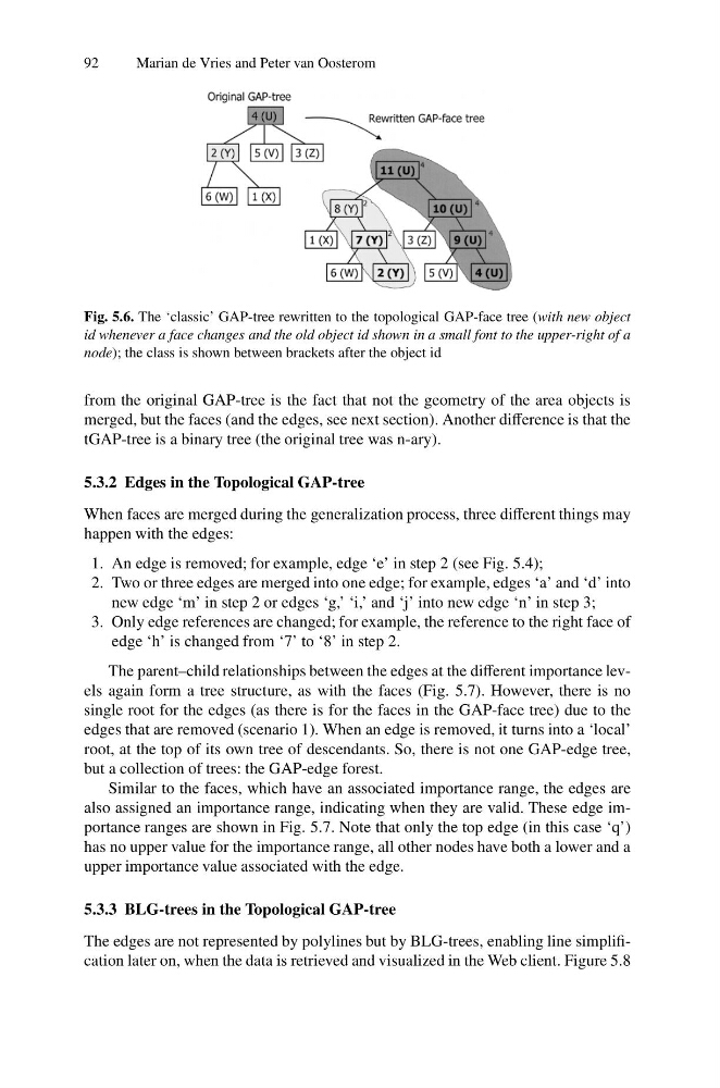
Fig. 5.6. The ‘classic’ GAP-tree rewritten to the topological GAP-face tree (with new object
id whenever a face changes and the old object id shown in a small font to the upper-right of a
node); the class is shown between brackets after the object id
from the original GAP-tree is the fact that not the geometry of the area objects is
merged, but the faces (and the edges, see next section). Another difference is that the
tGAP-tree is a binary tree (the original tree was n-ary).
5.3.2 Edges in the Topological GAP-tree
When faces are merged during the generalization process, three different things may
happen with the edges:
1. An edge is removed; for example, edge ‘e’ in step 2 (see Fig. 5.4);
2. Two or three edges are merged into one edge; for example, edges ‘a’ and ‘d’ into
new edge ‘m’ in step 2 or edges ‘g,’ ‘i,’ and ‘j’ into new edge ‘n’ in step 3;
3. Only edge references are changed; for example, the reference to the right face of
edge ‘h’ is changed from ‘7’ to ‘8’ in step 2.
The parent–child relationships between the edges at the different importance levels again form a tree structure, as with the faces (Fig. 5.7). However, there is no
single root for the edges (as there is for the faces in the GAP-face tree) due to the
edges that are removed (scenario 1). When an edge is removed, it turns into a ‘local’
root, at the top of its own tree of descendants. So, there is not one GAP-edge tree,
but a collection of trees: the GAP-edge forest.
Similar to the faces, which have an associated importance range, the edges are
also assigned an importance range, indicating when they are valid. These edge importance ranges are shown in Fig. 5.7. Note that only the top edge (in this case ‘q’)
has no upper value for the importance range, all other nodes have both a lower and a
upper importance value associated with the edge.
5.3.3 BLG-trees in the Topological GAP-tree
The edges are not represented by polylines but by BLG-trees, enabling line simplification later on, when the data is retrieved and visualized in the Web client. Figure 5.8
Marian de Vries and Peter van Oosterom
Fig. 5.6. The ‘classic’ GAP-tree rewritten to the topological GAP-face tree (with new object
id whenever a face changes and the old object id shown in a small font to the upper-right of a
node); the class is shown between brackets after the object id
from the original GAP-tree is the fact that not the geometry of the area objects is
merged, but the faces (and the edges, see next section). Another difference is that the
tGAP-tree is a binary tree (the original tree was n-ary).
5.3.2 Edges in the Topological GAP-tree
When faces are merged during the generalization process, three different things may
happen with the edges:
1. An edge is removed; for example, edge ‘e’ in step 2 (see Fig. 5.4);
2. Two or three edges are merged into one edge; for example, edges ‘a’ and ‘d’ into
new edge ‘m’ in step 2 or edges ‘g,’ ‘i,’ and ‘j’ into new edge ‘n’ in step 3;
3. Only edge references are changed; for example, the reference to the right face of
edge ‘h’ is changed from ‘7’ to ‘8’ in step 2.
The parent–child relationships between the edges at the different importance levels again form a tree structure, as with the faces (Fig. 5.7). However, there is no
single root for the edges (as there is for the faces in the GAP-face tree) due to the
edges that are removed (scenario 1). When an edge is removed, it turns into a ‘local’
root, at the top of its own tree of descendants. So, there is not one GAP-edge tree,
but a collection of trees: the GAP-edge forest.
Similar to the faces, which have an associated importance range, the edges are
also assigned an importance range, indicating when they are valid. These edge importance ranges are shown in Fig. 5.7. Note that only the top edge (in this case ‘q’)
has no upper value for the importance range, all other nodes have both a lower and a
upper importance value associated with the edge.
5.3.3 BLG-trees in the Topological GAP-tree
The edges are not represented by polylines but by BLG-trees, enabling line simplification later on, when the data is retrieved and visualized in the Web client. Figure 5.8