

another light sources (Lichtenthaler et al. 2013; Röttgers 2007) or even lasers and
laser diodes (Thoren and Schmidhalter 2009; Kolber et al. 2005; Schächtl et al.
2005). In this stage, it is advisable to add an optical filter with the aim to avoid
noise that light source can emit in chlorophyll fluorescence area.
After the chlorophyll excitation on the second stage, it is necessary to acquire
fluorescence response, there are different devices to apply in this stage according
with the applications, commonly it is used the photodiode, because it could be
easier to instrument and inexpensive option (Fedack et al. 2005; Kissinger and
Wilson 2011). Other option is the employment of photomultipliers for finer and
more sensitive applications (Bürling et al. 2011; Hunsche et al. 2011). In this stage,
it is critical the use of optical filters in order to avoid the light source or environmental noise and have, as a result, a fluorometer capable of measuring the
fluorescence lifetime of the sample.
13.9.1 Types of Fluorometers
There are many fluorometers in the market to meet the different needs and
applications. The Pump and Probe Fluorometer (P&P) (Falkowski et al. 1986)
works with a methodology to obtain the main chlorophyll fluorescence values
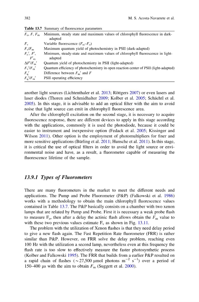
contained in Table 13.7. The P&P basically consists on a chamber with two xenon
lamps that are related by Pump and Probe. First it is necessary a weak probe flash
to measure F o , then after a delay the actinic flash allows obtain the F m value to
with these two previous values estimate F v as shown in Fig. 13.11.
The problem with the utilization of Xenon flashes is that they need delay period
to give a new flash again. The Fast Repetition Rate fluorometer (FRR) is rather
similar than P&P. However, on FRR solve the delay problem, reaching even
100 Hz with the utilization a second lamp, nevertheless even at this frequency the
flash rate is too slow to effectively measure the faster photosynthetic process
(Kolber and Falkowski 1995). The FRR that builds from a earlier P&P resulted on
a rapid chain of flashes (*27,500 lmol photons m
-2 s
-1 ) over a period of
150–400 ls with the aim to obtain F m (Suggett et al. 2000).
Table 13.7 Summary of fluorescence parameters
F o , F, F m Minimum, steady state and maximum values of chlorophyll fluorescence in darkadapted
F v
Variable fluorescence (F m –F o )
F v /F m
Maximum quantum yield of photochemistry in PSII (dark-adapted)
F o
0 , F
0 ,
F
0
m
Minimum, steady-state and maximum values of chlorophyll fluorescence in lightadapted
DF
0 /F m
0
Quantum yield of photochemistry in PSII (light-adapted)
F v
0 /F m
0
Quantum efficiency of photochemistry in open reaction center of PSII (light-adapted)
F q
0
Difference between F m
0 and F
F q
0 /F m
0
PSII operating efficiency
382
M. S. Acosta-Navarrete et al.
laser diodes (Thoren and Schmidhalter 2009; Kolber et al. 2005; Schächtl et al.
2005). In this stage, it is advisable to add an optical filter with the aim to avoid
noise that light source can emit in chlorophyll fluorescence area.
After the chlorophyll excitation on the second stage, it is necessary to acquire
fluorescence response, there are different devices to apply in this stage according
with the applications, commonly it is used the photodiode, because it could be
easier to instrument and inexpensive option (Fedack et al. 2005; Kissinger and
Wilson 2011). Other option is the employment of photomultipliers for finer and
more sensitive applications (Bürling et al. 2011; Hunsche et al. 2011). In this stage,
it is critical the use of optical filters in order to avoid the light source or environmental noise and have, as a result, a fluorometer capable of measuring the
fluorescence lifetime of the sample.
13.9.1 Types of Fluorometers
There are many fluorometers in the market to meet the different needs and
applications. The Pump and Probe Fluorometer (P&P) (Falkowski et al. 1986)
works with a methodology to obtain the main chlorophyll fluorescence values
contained in Table 13.7. The P&P basically consists on a chamber with two xenon
lamps that are related by Pump and Probe. First it is necessary a weak probe flash
to measure F o , then after a delay the actinic flash allows obtain the F m value to
with these two previous values estimate F v as shown in Fig. 13.11.
The problem with the utilization of Xenon flashes is that they need delay period
to give a new flash again. The Fast Repetition Rate fluorometer (FRR) is rather
similar than P&P. However, on FRR solve the delay problem, reaching even
100 Hz with the utilization a second lamp, nevertheless even at this frequency the
flash rate is too slow to effectively measure the faster photosynthetic process
(Kolber and Falkowski 1995). The FRR that builds from a earlier P&P resulted on
a rapid chain of flashes (*27,500 lmol photons m
-2 s
-1 ) over a period of
150–400 ls with the aim to obtain F m (Suggett et al. 2000).
Table 13.7 Summary of fluorescence parameters
F o , F, F m Minimum, steady state and maximum values of chlorophyll fluorescence in darkadapted
F v
Variable fluorescence (F m –F o )
F v /F m
Maximum quantum yield of photochemistry in PSII (dark-adapted)
F o
0 , F
0 ,
F
0
m
Minimum, steady-state and maximum values of chlorophyll fluorescence in lightadapted
DF
0 /F m
0
Quantum yield of photochemistry in PSII (light-adapted)
F v
0 /F m
0
Quantum efficiency of photochemistry in open reaction center of PSII (light-adapted)
F q
0
Difference between F m
0 and F
F q
0 /F m
0
PSII operating efficiency
382
M. S. Acosta-Navarrete et al.