

+:0
<.,;.)
+:0
!-<
r-'
;l>
a
'<
l»
::l
Ct>
....
~
$')
I I II: I I I Behind
Below
(D)
Above
Below
(B)
Above
(A)
Skull, Soft TIssue & Air Sacs Model
(e)
Freq=25kHz; (9,$)=(13.9.-1.4); DI=11.6dB
1
~
Freq=50kHz; (9.$)=(4.2.-7.9); DI=13.8dB
0.1 ------0.2 .------.
0.3
.
0.4 ------.
0.5 ------0.6 -------.0.7 ------..0.8 ----.-.0 . 9 - -
II I ~
I i'~':;ir \
~
III
Behind
::<:~-!.:;'.:i
Behind Behind I I I IR I
I:.;
1
0.8
0.6
0.4
0.2
a
FIGURE
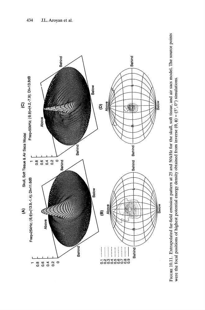
10.11. Extrapolated far-field emission pattern at 25 and 50 kHz for the skull, soft tissue, and air sacs model. The source points
were the focal positions of highest potential energy density obtained from inverse (8,
$)
=(5°,0°) simulations.
<.,;.)
+:0
!-<
r-'
;l>
a
'<
l»
::l
Ct>
....
~
$')
I I II: I I I Behind
Below
(D)
Above
Below
(B)
Above
(A)
Skull, Soft TIssue & Air Sacs Model
(e)
Freq=25kHz; (9,$)=(13.9.-1.4); DI=11.6dB
1
~
Freq=50kHz; (9.$)=(4.2.-7.9); DI=13.8dB
0.1 ------0.2 .------.
0.3
.
0.4 ------.
0.5 ------0.6 -------.0.7 ------..0.8 ----.-.0 . 9 - -
II I ~
I i'~':;ir \
~
III
Behind
::<:~-!.:;'.:i
Behind Behind I I I IR I
I:.;
1
0.8
0.6
0.4
0.2
a
FIGURE
10.11. Extrapolated far-field emission pattern at 25 and 50 kHz for the skull, soft tissue, and air sacs model. The source points
were the focal positions of highest potential energy density obtained from inverse (8,
$)
=(5°,0°) simulations.