

116
4 . SIMULATING GROWTH AND FORM
by the sink nodes: the nodes adjacent to the growth form. The tracer particles can travel from a node at site x in the lattice to one of the 18 adjacent
nodes x + ci, where the Pe number in (2.4) determines if flow or diffusion
dominates. When flow dominates, most particles will move in the direction
of the governing flow, while under diffusion dominated conditions the number of particles which travel in each of the 18 directions will be approximately
equal. In the simulations the diffusion coefficient D varies, and it is kept constant by adjusting the driving force F of the system. Due to the growth of the
aggregate the velocity in the free fluid would gradually decrease if the driving
force were not adjusted.
4.5.3 Growth by Aggregation in a Monodirectional Flow
In the aggregation process the growth process is modeled as in the Diffusion
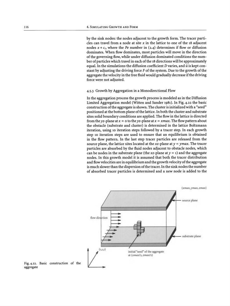
Limited Aggregation model (Witten and Sander 1981). In Fig. 4.22 the basic
construction of the aggregate is shown. The cluster is initialized with a "seed"
positioned at the bottom plane of the lattice. In both the cluster and substrate
sites solid boundary conditions are applied . The flow in the lattice is directed
from the yz-plane at x =0 to the yz-plane at x =xmax. The flowpattern about
the obstacle (substrate and cluster) is determined in the lattice Boltzmann
iteration, using 10 iteration steps followed by a tracer step. In each growth
step 10 iteration steps are used to ensure that an equilibrium is obtained
in the flow pattern. In the last step tracer particles are released from the
source plane , the lattice sites located at the xz-plane at y = ymax. The tracer
particles are absorbed by the fluid nodes adjacent to obstacle nodes, which
can be nodes in the substrate plane (the xz-plane at y = 1) and the aggregate
nodes. In this growth model it is assumed that both the tracer distribution
and flowvelocities are in equilibrium and the growth velocity of the aggregate
is much slower than the dispersion of the tracer. In the sink nodes the number
of absorbed tracer particles is determined and a new node is added to the
(xmax,ymax. zmax )
__- - substrate plane
__orT- source plane
initial "seed" of the aggregate
at txmax h ;zmaxh)
flow dir
Fig. 4.22. Basic construction of the
aggregate
4 . SIMULATING GROWTH AND FORM
by the sink nodes: the nodes adjacent to the growth form. The tracer particles can travel from a node at site x in the lattice to one of the 18 adjacent
nodes x + ci, where the Pe number in (2.4) determines if flow or diffusion
dominates. When flow dominates, most particles will move in the direction
of the governing flow, while under diffusion dominated conditions the number of particles which travel in each of the 18 directions will be approximately
equal. In the simulations the diffusion coefficient D varies, and it is kept constant by adjusting the driving force F of the system. Due to the growth of the
aggregate the velocity in the free fluid would gradually decrease if the driving
force were not adjusted.
4.5.3 Growth by Aggregation in a Monodirectional Flow
In the aggregation process the growth process is modeled as in the Diffusion
Limited Aggregation model (Witten and Sander 1981). In Fig. 4.22 the basic
construction of the aggregate is shown. The cluster is initialized with a "seed"
positioned at the bottom plane of the lattice. In both the cluster and substrate
sites solid boundary conditions are applied . The flow in the lattice is directed
from the yz-plane at x =0 to the yz-plane at x =xmax. The flowpattern about
the obstacle (substrate and cluster) is determined in the lattice Boltzmann
iteration, using 10 iteration steps followed by a tracer step. In each growth
step 10 iteration steps are used to ensure that an equilibrium is obtained
in the flow pattern. In the last step tracer particles are released from the
source plane , the lattice sites located at the xz-plane at y = ymax. The tracer
particles are absorbed by the fluid nodes adjacent to obstacle nodes, which
can be nodes in the substrate plane (the xz-plane at y = 1) and the aggregate
nodes. In this growth model it is assumed that both the tracer distribution
and flowvelocities are in equilibrium and the growth velocity of the aggregate
is much slower than the dispersion of the tracer. In the sink nodes the number
of absorbed tracer particles is determined and a new node is added to the
(xmax,ymax. zmax )
__- - substrate plane
__orT- source plane
initial "seed" of the aggregate
at txmax h ;zmaxh)
flow dir
Fig. 4.22. Basic construction of the
aggregate