

Equipment and techniques
Dredging has been conducted by a wide range of equipment
and schemes and for a wide variety of purposes (U.S. Army
Corps of Engineers, 1983; Huston, 1986; Herbich, 1992;
Bray et al., 1996; PIANC, 2009; Bray and Cohen, 2010).
Most approaches are categorized as either mechanical or
hydraulic, with the latter referring to a scheme that involves
pumping a water-sediment slurry, often after mechanical
loosening of the material being dredged.
A steel I-beam or other device dragged across an underwater high spot can remove a navigation hazard by
redistributing sediment underwater and is thus a crude
form of mechanical dredging. A clamshell bucket
deployed from a standard construction crane on
a floating barge can remove submarine sediment and is
another example of a mechanical approach. Likewise
a backhoe on a barge can function as a dredge in shallow
water. Material can be deposited on or in a barge or truck
and hauled away for offshore or onshore disposal.
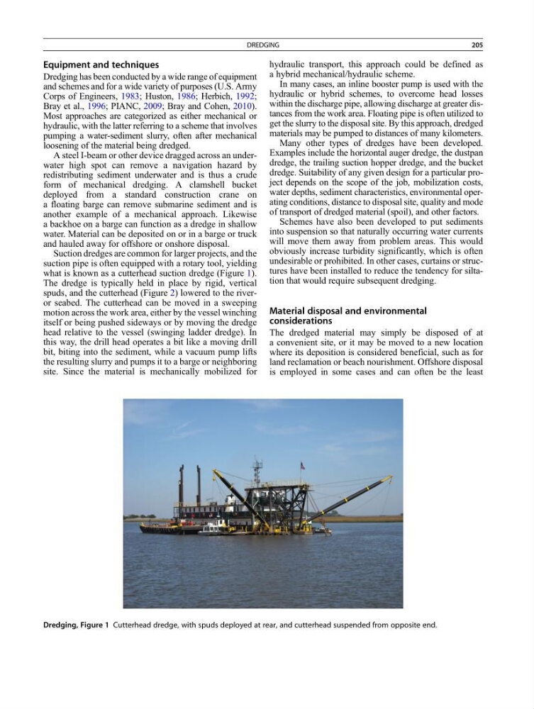
Suction dredges are common for larger projects, and the
suction pipe is often equipped with a rotary tool, yielding
what is known as a cutterhead suction dredge (Figure 1).
The dredge is typically held in place by rigid, vertical
spuds, and the cutterhead (Figure 2) lowered to the riveror seabed. The cutterhead can be moved in a sweeping
motion across the work area, either by the vessel winching
itself or being pushed sideways or by moving the dredge
head relative to the vessel (swinging ladder dredge). In
this way, the drill head operates a bit like a moving drill
bit, biting into the sediment, while a vacuum pump lifts
the resulting slurry and pumps it to a barge or neighboring
site. Since the material is mechanically mobilized for
hydraulic transport, this approach could be defined as
a hybrid mechanical/hydraulic scheme.
In many cases, an inline booster pump is used with the
hydraulic or hybrid schemes, to overcome head losses
within the discharge pipe, allowing discharge at greater distances from the work area. Floating pipe is often utilized to
get the slurry to the disposal site. By this approach, dredged
materials may be pumped to distances of many kilometers.
Many other types of dredges have been developed.
Examples include the horizontal auger dredge, the dustpan
dredge, the trailing suction hopper dredge, and the bucket
dredge. Suitability of any given design for a particular project depends on the scope of the job, mobilization costs,
water depths, sediment characteristics, environmental operating conditions, distance to disposal site, quality and mode
of transport of dredged material (spoil), and other factors.
Schemes have also been developed to put sediments
into suspension so that naturally occurring water currents
will move them away from problem areas. This would
obviously increase turbidity significantly, which is often
undesirable or prohibited. In other cases, curtains or structures have been installed to reduce the tendency for siltation that would require subsequent dredging.
Material disposal and environmental
considerations
The dredged material may simply be disposed of at
a convenient site, or it may be moved to a new location
where its deposition is considered beneficial, such as for
land reclamation or beach nourishment. Offshore disposal
is employed in some cases and can often be the least
Dredging, Figure 1 Cutterhead dredge, with spuds deployed at rear, and cutterhead suspended from opposite end.
DREDGING
205
Dredging has been conducted by a wide range of equipment
and schemes and for a wide variety of purposes (U.S. Army
Corps of Engineers, 1983; Huston, 1986; Herbich, 1992;
Bray et al., 1996; PIANC, 2009; Bray and Cohen, 2010).
Most approaches are categorized as either mechanical or
hydraulic, with the latter referring to a scheme that involves
pumping a water-sediment slurry, often after mechanical
loosening of the material being dredged.
A steel I-beam or other device dragged across an underwater high spot can remove a navigation hazard by
redistributing sediment underwater and is thus a crude
form of mechanical dredging. A clamshell bucket
deployed from a standard construction crane on
a floating barge can remove submarine sediment and is
another example of a mechanical approach. Likewise
a backhoe on a barge can function as a dredge in shallow
water. Material can be deposited on or in a barge or truck
and hauled away for offshore or onshore disposal.
Suction dredges are common for larger projects, and the
suction pipe is often equipped with a rotary tool, yielding
what is known as a cutterhead suction dredge (Figure 1).
The dredge is typically held in place by rigid, vertical
spuds, and the cutterhead (Figure 2) lowered to the riveror seabed. The cutterhead can be moved in a sweeping
motion across the work area, either by the vessel winching
itself or being pushed sideways or by moving the dredge
head relative to the vessel (swinging ladder dredge). In
this way, the drill head operates a bit like a moving drill
bit, biting into the sediment, while a vacuum pump lifts
the resulting slurry and pumps it to a barge or neighboring
site. Since the material is mechanically mobilized for
hydraulic transport, this approach could be defined as
a hybrid mechanical/hydraulic scheme.
In many cases, an inline booster pump is used with the
hydraulic or hybrid schemes, to overcome head losses
within the discharge pipe, allowing discharge at greater distances from the work area. Floating pipe is often utilized to
get the slurry to the disposal site. By this approach, dredged
materials may be pumped to distances of many kilometers.
Many other types of dredges have been developed.
Examples include the horizontal auger dredge, the dustpan
dredge, the trailing suction hopper dredge, and the bucket
dredge. Suitability of any given design for a particular project depends on the scope of the job, mobilization costs,
water depths, sediment characteristics, environmental operating conditions, distance to disposal site, quality and mode
of transport of dredged material (spoil), and other factors.
Schemes have also been developed to put sediments
into suspension so that naturally occurring water currents
will move them away from problem areas. This would
obviously increase turbidity significantly, which is often
undesirable or prohibited. In other cases, curtains or structures have been installed to reduce the tendency for siltation that would require subsequent dredging.
Material disposal and environmental
considerations
The dredged material may simply be disposed of at
a convenient site, or it may be moved to a new location
where its deposition is considered beneficial, such as for
land reclamation or beach nourishment. Offshore disposal
is employed in some cases and can often be the least
Dredging, Figure 1 Cutterhead dredge, with spuds deployed at rear, and cutterhead suspended from opposite end.
DREDGING
205