

Novel Bioreactors for Culturing Marine Organisms 12.8 High-Temperature and/or High-Pressure Bioreactors (HP-/HTBR) 379
Part B | 12.8
N 2 + CO 2
p low
CH 4
CH 4
Medium
(anoxic)
Reservoirs
Pressurization
stage 1
Pressurization
stage 2
Incubation
Gas saturation
Incubation
manifold
Gas-medium
reactor
HP-MI system
HP-CI system
P1
R3
R2
B1
Analysis
Bioreactor
Medium
p 1
N 2
+
CO 2
p low
p 0
p 1
p 3
p 2
p 2
p 3
p 1 (p 1 < p 1 ; p 3 )
R1
p 1
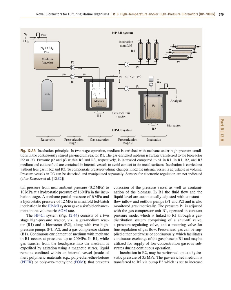
Fig. 12.44 Incubation principle. In two-stage operation, medium is enriched with methane under high-pressure conditions in the continuously stirred gas-medium reactor R1. The gas-enriched medium is further transferred to the bioreactor
R2 or R3. Pressure p2 and p3 within R2 and R3, respectively, is increased compared to p1 in R1. In R1, R2, and R3
medium and culture fluid are contained in internal vessels to avoid contact to the metal surfaces. Incubation is carried out
without free gas in R2 and R3. To compensate pressure/volume changes in R2 the internal vessel is adjustable in volume.
Pressure vessels in R3 can be detached and manipulated separately. Sensors for electronic regulation are not indicated
(after Deusner et al. [12.82])
tial pressure from near ambient pressure (0:2 MPa) to
10 MPa at a hydrostatic pressure of 16 MPa in the incubation stage. A methane partial pressure of 6 MPa and
a hydrostatic pressure of 12 MPa in manifold fed-batch
incubation in the HP-MI system gave a sixfold enhancement in the volumetric AOM rate.
The HP-CI system (Fig. 12.44) consists of a two
stage high-pressure reactor, viz., a gas-medium reactor (R1) and a bioreactor (R2), along with two highpressure pumps (P1, P2), and a gas compressor station
(B1). Continuous enrichment of medium with methane
in R1 occurs at pressures up to 20 MPa. In R1, while
gas transfer from the headspace into the medium is
expedited by agitation using a magnetic stirrer, liquid
remains confined within an internal vessel (made of
inert polymeric materials e.g., poly-ether-ether-ketone
(PEEK) or poly-oxy-methylene (POM)) that prevents
corrosion of the pressure vessel as well as contamination of the biomass. In R1 the fluid flow and the
liquid level are automatically adjusted with constant –
flow inflow and outflow pumps (P1 and P2) and is also
monitored gravimetrically. The pressure P1 is adjusted
with the gas compressor unit B1, operated in constant
pressure mode, which is linked to R1 through a gasdistribution system comprising of a shut-off valve,
a pressure-regulating valve, and a metering valve for
fine regulation of gas flow. Pressurized gas can be supplied either batchwise or continuously, which facilitates
continuous exchange of the gas phase in R1 and may be
utilized for supply of low-concentration gaseous substrates during continuous operation.
Incubation in R2, may be performed up to a hydrostatic pressure of 35 MPa. The gas-enriched medium is
transferred to R2 via pump P2 which is set to increase
Part B | 12.8
N 2 + CO 2
p low
CH 4
CH 4
Medium
(anoxic)
Reservoirs
Pressurization
stage 1
Pressurization
stage 2
Incubation
Gas saturation
Incubation
manifold
Gas-medium
reactor
HP-MI system
HP-CI system
P1
R3
R2
B1
Analysis
Bioreactor
Medium
p 1
N 2
+
CO 2
p low
p 0
p 1
p 3
p 2
p 2
p 3
p 1 (p 1 < p 1 ; p 3 )
R1
p 1
Fig. 12.44 Incubation principle. In two-stage operation, medium is enriched with methane under high-pressure conditions in the continuously stirred gas-medium reactor R1. The gas-enriched medium is further transferred to the bioreactor
R2 or R3. Pressure p2 and p3 within R2 and R3, respectively, is increased compared to p1 in R1. In R1, R2, and R3
medium and culture fluid are contained in internal vessels to avoid contact to the metal surfaces. Incubation is carried out
without free gas in R2 and R3. To compensate pressure/volume changes in R2 the internal vessel is adjustable in volume.
Pressure vessels in R3 can be detached and manipulated separately. Sensors for electronic regulation are not indicated
(after Deusner et al. [12.82])
tial pressure from near ambient pressure (0:2 MPa) to
10 MPa at a hydrostatic pressure of 16 MPa in the incubation stage. A methane partial pressure of 6 MPa and
a hydrostatic pressure of 12 MPa in manifold fed-batch
incubation in the HP-MI system gave a sixfold enhancement in the volumetric AOM rate.
The HP-CI system (Fig. 12.44) consists of a two
stage high-pressure reactor, viz., a gas-medium reactor (R1) and a bioreactor (R2), along with two highpressure pumps (P1, P2), and a gas compressor station
(B1). Continuous enrichment of medium with methane
in R1 occurs at pressures up to 20 MPa. In R1, while
gas transfer from the headspace into the medium is
expedited by agitation using a magnetic stirrer, liquid
remains confined within an internal vessel (made of
inert polymeric materials e.g., poly-ether-ether-ketone
(PEEK) or poly-oxy-methylene (POM)) that prevents
corrosion of the pressure vessel as well as contamination of the biomass. In R1 the fluid flow and the
liquid level are automatically adjusted with constant –
flow inflow and outflow pumps (P1 and P2) and is also
monitored gravimetrically. The pressure P1 is adjusted
with the gas compressor unit B1, operated in constant
pressure mode, which is linked to R1 through a gasdistribution system comprising of a shut-off valve,
a pressure-regulating valve, and a metering valve for
fine regulation of gas flow. Pressurized gas can be supplied either batchwise or continuously, which facilitates
continuous exchange of the gas phase in R1 and may be
utilized for supply of low-concentration gaseous substrates during continuous operation.
Incubation in R2, may be performed up to a hydrostatic pressure of 35 MPa. The gas-enriched medium is
transferred to R2 via pump P2 which is set to increase