

Part B | 12.2
336 Part B Tools and Methods in Marine Biotechnology
Photo-bioreactor
Pump
CO 2 gas
Air gas
Gas mixer
Flow meter
Flow meter
Humidifier
Valve
Diffusor
Baffle
Medium
Fluorescent
lamps
Cover
Fluorescent
lamps
Biomass
sampling
port
90 cm
20 cm
70 cm
a)
b)
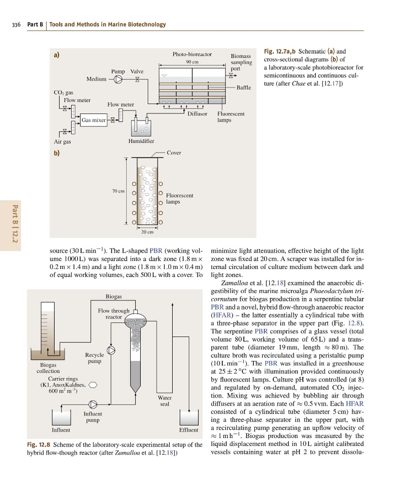
Fig. 12.7a,b Schematic (a) and
cross-sectional diagrams (b) of
a laboratory-scale photobioreactor for
semicontinuous and continuous culture (after Chae et al. [12.17])
source (30 L min
1 ). The L-shaped PBR (working volume 1000 L) was separated into a dark zone (1:8 m
0:2 m 1:4 m) and a light zone (1:8 m 1:0 m 0:4 m)
of equal working volumes, each 500 L with a cover. To
Biogas
Biogas
collection
Carrier rings
(K1, AnoxKaldnes,
600 m
2 m
–3
)
Recycle
pump
Influent
pump
Water
seal
Influent
Effluent
Flow through
reactor
Fig. 12.8 Scheme of the laboratory-scale experimental setup of the
hybrid flow-though reactor (after Zamalloa et al. [12.18])
minimize light attenuation, effective height of the light
zone was fixed at 20 cm. A scraper was installed for internal circulation of culture medium between dark and
light zones.
Zamalloa et al. [12.18] examined the anaerobic digestibility of the marine microalga Phaeodactylum tricornutum for biogas production in a serpentine tubular
PBR and a novel, hybrid flow-through anaerobic reactor
(HFAR) – the latter essentially a cylindrical tube with
a three-phase separator in the upper part (Fig. 12.8).
The serpentine PBR comprises of a glass vessel (total
volume 80 L, working volume of 65 L) and a transparent tube (diameter 19 mm, length 80 m). The
culture broth was recirculated using a peristaltic pump
(10 L min
1 ). The PBR was installed in a greenhouse
at 25 ˙ 2
ı C with illumination provided continuously
by fluorescent lamps. Culture pH was controlled (at 8)
and regulated by on-demand, automated CO 2 injection. Mixing was achieved by bubbling air through
diffusers at an aeration rate of 0:5 vvm. Each HFAR
consisted of a cylindrical tube (diameter 5 cm) having a three-phase separator in the upper part, with
a recirculating pump generating an upflow velocity of
1 m h
1 . Biogas production was measured by the
liquid displacement method in 10 L airtight calibrated
vessels containing water at pH 2 to prevent dissolu-
336 Part B Tools and Methods in Marine Biotechnology
Photo-bioreactor
Pump
CO 2 gas
Air gas
Gas mixer
Flow meter
Flow meter
Humidifier
Valve
Diffusor
Baffle
Medium
Fluorescent
lamps
Cover
Fluorescent
lamps
Biomass
sampling
port
90 cm
20 cm
70 cm
a)
b)
Fig. 12.7a,b Schematic (a) and
cross-sectional diagrams (b) of
a laboratory-scale photobioreactor for
semicontinuous and continuous culture (after Chae et al. [12.17])
source (30 L min
1 ). The L-shaped PBR (working volume 1000 L) was separated into a dark zone (1:8 m
0:2 m 1:4 m) and a light zone (1:8 m 1:0 m 0:4 m)
of equal working volumes, each 500 L with a cover. To
Biogas
Biogas
collection
Carrier rings
(K1, AnoxKaldnes,
600 m
2 m
–3
)
Recycle
pump
Influent
pump
Water
seal
Influent
Effluent
Flow through
reactor
Fig. 12.8 Scheme of the laboratory-scale experimental setup of the
hybrid flow-though reactor (after Zamalloa et al. [12.18])
minimize light attenuation, effective height of the light
zone was fixed at 20 cm. A scraper was installed for internal circulation of culture medium between dark and
light zones.
Zamalloa et al. [12.18] examined the anaerobic digestibility of the marine microalga Phaeodactylum tricornutum for biogas production in a serpentine tubular
PBR and a novel, hybrid flow-through anaerobic reactor
(HFAR) – the latter essentially a cylindrical tube with
a three-phase separator in the upper part (Fig. 12.8).
The serpentine PBR comprises of a glass vessel (total
volume 80 L, working volume of 65 L) and a transparent tube (diameter 19 mm, length 80 m). The
culture broth was recirculated using a peristaltic pump
(10 L min
1 ). The PBR was installed in a greenhouse
at 25 ˙ 2
ı C with illumination provided continuously
by fluorescent lamps. Culture pH was controlled (at 8)
and regulated by on-demand, automated CO 2 injection. Mixing was achieved by bubbling air through
diffusers at an aeration rate of 0:5 vvm. Each HFAR
consisted of a cylindrical tube (diameter 5 cm) having a three-phase separator in the upper part, with
a recirculating pump generating an upflow velocity of
1 m h
1 . Biogas production was measured by the
liquid displacement method in 10 L airtight calibrated
vessels containing water at pH 2 to prevent dissolu-