

Part B | 9.4
286 Part B Tools and Methods in Marine Biotechnology
9.4.4 Process Scale-Up
and Other Limiting Factors
Process scale-up seeks to preserve the performance of
a given photobioreactor design as it is moved from
a laboratory scale to a process scale. Conservatively,
process scale-up is carried out in increments of ten.
For example, a 100 L laboratory photobioreactor is first
scaled up to a 1000 L pilot-plant photobioreactor, which
is then scaled up to a 10 000 L process-scale photobioreactor. The scale-up design of the photobioreactor
follows a few simple guidelines if the five-step process
for rational photobioreactor design described at the beginning of this section is followed. Scale-up guidelines
for bubble-column airlift photobioreactors and tubular
photobioreactors are suggested below.
Process scale-up for bubble-column and airlift photobioreactors requires that the mean light intensity (I m )
and volumetric CO 2 transfer rate (CO 2 -TR) are kept
constant as the vessel size is increased. Therefore, the
width of the planar vessel or the diameter of the cylindrical vessel is usually kept constant as the vessel size
is increased from the pilot scale to the process scale to
preserve I m . The incident light intensity to the vessel
surface is also kept constant. The other vessel dimensions (height or length of the planar vessel, height of
the cylindrical vessel) are increased until the vessel size
reaches 2000 L. If culture volumes in excess of 2000 L
are required, then it is best to construct multiple units
operating in parallel. Once the final vessel size is determined, the aeration rate is increased to keep the aeration
rate per unit volume constant from the pilot scale to the
process scale. For example, if the required aeration rate
is 20 L air min
1 for a 100 L vessel, then the required
CO 2 (g)
Air
Medium
Light
source
Side View
Irradiance sensor
(incident)
Irradiance sensor
(transmitted)
F
F
L
F
O pH
IR
IR F
O pH T
F
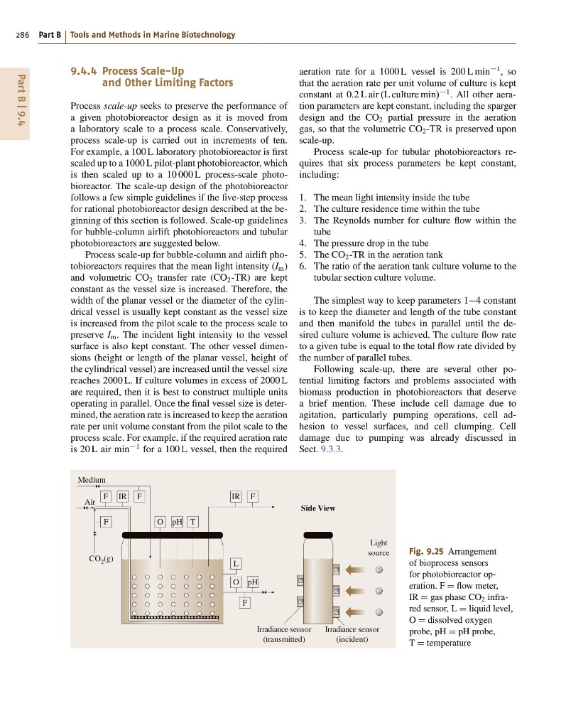
Fig. 9.25 Arrangement
of bioprocess sensors
for photobioreactor operation. F D flow meter,
IR D gas phase CO 2 infrared sensor, L D liquid level,
O D dissolved oxygen
probe, pH D pH probe,
T D temperature
aeration rate for a 1000 L vessel is 200 L min
1 , so
that the aeration rate per unit volume of culture is kept
constant at 0:2 L air .L culture min/
1 . All other aeration parameters are kept constant, including the sparger
design and the CO 2 partial pressure in the aeration
gas, so that the volumetric CO 2 -TR is preserved upon
scale-up.
Process scale-up for tubular photobioreactors requires that six process parameters be kept constant,
including:
1. The mean light intensity inside the tube
2. The culture residence time within the tube
3. The Reynolds number for culture flow within the
tube
4. The pressure drop in the tube
5. The CO 2 -TR in the aeration tank
6. The ratio of the aeration tank culture volume to the
tubular section culture volume.
The simplest way to keep parameters 14 constant
is to keep the diameter and length of the tube constant
and then manifold the tubes in parallel until the desired culture volume is achieved. The culture flow rate
to a given tube is equal to the total flow rate divided by
the number of parallel tubes.
Following scale-up, there are several other potential limiting factors and problems associated with
biomass production in photobioreactors that deserve
a brief mention. These include cell damage due to
agitation, particularly pumping operations, cell adhesion to vessel surfaces, and cell clumping. Cell
damage due to pumping was already discussed in
Sect. 9.3.3.
286 Part B Tools and Methods in Marine Biotechnology
9.4.4 Process Scale-Up
and Other Limiting Factors
Process scale-up seeks to preserve the performance of
a given photobioreactor design as it is moved from
a laboratory scale to a process scale. Conservatively,
process scale-up is carried out in increments of ten.
For example, a 100 L laboratory photobioreactor is first
scaled up to a 1000 L pilot-plant photobioreactor, which
is then scaled up to a 10 000 L process-scale photobioreactor. The scale-up design of the photobioreactor
follows a few simple guidelines if the five-step process
for rational photobioreactor design described at the beginning of this section is followed. Scale-up guidelines
for bubble-column airlift photobioreactors and tubular
photobioreactors are suggested below.
Process scale-up for bubble-column and airlift photobioreactors requires that the mean light intensity (I m )
and volumetric CO 2 transfer rate (CO 2 -TR) are kept
constant as the vessel size is increased. Therefore, the
width of the planar vessel or the diameter of the cylindrical vessel is usually kept constant as the vessel size
is increased from the pilot scale to the process scale to
preserve I m . The incident light intensity to the vessel
surface is also kept constant. The other vessel dimensions (height or length of the planar vessel, height of
the cylindrical vessel) are increased until the vessel size
reaches 2000 L. If culture volumes in excess of 2000 L
are required, then it is best to construct multiple units
operating in parallel. Once the final vessel size is determined, the aeration rate is increased to keep the aeration
rate per unit volume constant from the pilot scale to the
process scale. For example, if the required aeration rate
is 20 L air min
1 for a 100 L vessel, then the required
CO 2 (g)
Air
Medium
Light
source
Side View
Irradiance sensor
(incident)
Irradiance sensor
(transmitted)
F
F
L
F
O pH
IR
IR F
O pH T
F
Fig. 9.25 Arrangement
of bioprocess sensors
for photobioreactor operation. F D flow meter,
IR D gas phase CO 2 infrared sensor, L D liquid level,
O D dissolved oxygen
probe, pH D pH probe,
T D temperature
aeration rate for a 1000 L vessel is 200 L min
1 , so
that the aeration rate per unit volume of culture is kept
constant at 0:2 L air .L culture min/
1 . All other aeration parameters are kept constant, including the sparger
design and the CO 2 partial pressure in the aeration
gas, so that the volumetric CO 2 -TR is preserved upon
scale-up.
Process scale-up for tubular photobioreactors requires that six process parameters be kept constant,
including:
1. The mean light intensity inside the tube
2. The culture residence time within the tube
3. The Reynolds number for culture flow within the
tube
4. The pressure drop in the tube
5. The CO 2 -TR in the aeration tank
6. The ratio of the aeration tank culture volume to the
tubular section culture volume.
The simplest way to keep parameters 14 constant
is to keep the diameter and length of the tube constant
and then manifold the tubes in parallel until the desired culture volume is achieved. The culture flow rate
to a given tube is equal to the total flow rate divided by
the number of parallel tubes.
Following scale-up, there are several other potential limiting factors and problems associated with
biomass production in photobioreactors that deserve
a brief mention. These include cell damage due to
agitation, particularly pumping operations, cell adhesion to vessel surfaces, and cell clumping. Cell
damage due to pumping was already discussed in
Sect. 9.3.3.