

Bioprocess Engineering of Phototrophic Marine Organisms 9.4 Limiting Factors in Photobioreactor Design and Operation 279
Part B | 9.4
I 0
I (z)
I 0
I 0
I(z)
I(z) = I 1 (z)+I 2 (z)
I 1 (z)
I 2 (z)
α = 1
z = L
z
α = 2
z = L
z
Light
source 1
Light
source 2
a)
b)
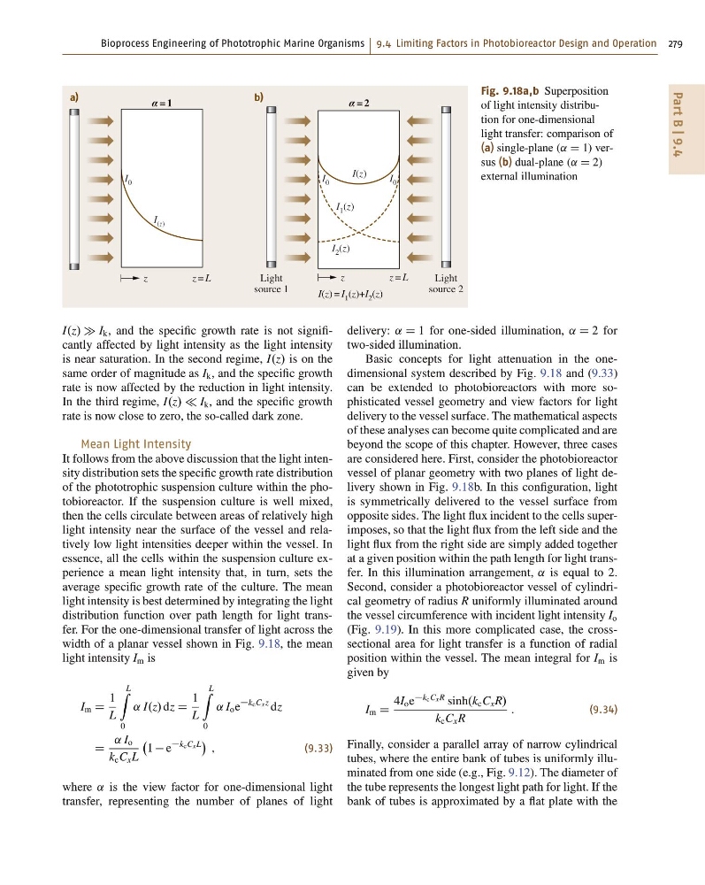
Fig. 9.18a,b Superposition
of light intensity distribution for one-dimensional
light transfer: comparison of
(a) single-plane (˛ D 1) versus (b) dual-plane (˛ D 2)
external illumination
I.z/ I k , and the specific growth rate is not significantly affected by light intensity as the light intensity
is near saturation. In the second regime, I.z/ is on the
same order of magnitude as I k , and the specific growth
rate is now affected by the reduction in light intensity.
In the third regime, I.z/ I k , and the specific growth
rate is now close to zero, the so-called dark zone.
Mean Light Intensity
It follows from the above discussion that the light intensity distribution sets the specific growth rate distribution
of the phototrophic suspension culture within the photobioreactor. If the suspension culture is well mixed,
then the cells circulate between areas of relatively high
light intensity near the surface of the vessel and relatively low light intensities deeper within the vessel. In
essence, all the cells within the suspension culture experience a mean light intensity that, in turn, sets the
average specific growth rate of the culture. The mean
light intensity is best determined by integrating the light
distribution function over path length for light transfer. For the one-dimensional transfer of light across the
width of a planar vessel shown in Fig. 9.18, the mean
light intensity I m is
I m D
1
L
L
Z
0
˛ I.z/ dz D
1
L
L
Z
0
˛ I o e
kcCxz dz
D
˛ I o
k c C x L
1 e
kcCxL
;
(9.33)
where ˛ is the view factor for one-dimensional light
transfer, representing the number of planes of light
delivery: ˛ D 1 for one-sided illumination, ˛ D 2 for
two-sided illumination.
Basic concepts for light attenuation in the onedimensional system described by Fig. 9.18 and (9.33)
can be extended to photobioreactors with more sophisticated vessel geometry and view factors for light
delivery to the vessel surface. The mathematical aspects
of these analyses can become quite complicated and are
beyond the scope of this chapter. However, three cases
are considered here. First, consider the photobioreactor
vessel of planar geometry with two planes of light delivery shown in Fig. 9.18b. In this configuration, light
is symmetrically delivered to the vessel surface from
opposite sides. The light flux incident to the cells superimposes, so that the light flux from the left side and the
light flux from the right side are simply added together
at a given position within the path length for light transfer. In this illumination arrangement, ˛ is equal to 2.
Second, consider a photobioreactor vessel of cylindrical geometry of radius R uniformly illuminated around
the vessel circumference with incident light intensity I o
(Fig. 9.19). In this more complicated case, the crosssectional area for light transfer is a function of radial
position within the vessel. The mean integral for I m is
given by
I m D
4I o e
kcCxR sinh.k c C x R/
k c C x R
:
(9.34)
Finally, consider a parallel array of narrow cylindrical
tubes, where the entire bank of tubes is uniformly illuminated from one side (e.g., Fig. 9.12). The diameter of
the tube represents the longest light path for light. If the
bank of tubes is approximated by a flat plate with the
Part B | 9.4
I 0
I (z)
I 0
I 0
I(z)
I(z) = I 1 (z)+I 2 (z)
I 1 (z)
I 2 (z)
α = 1
z = L
z
α = 2
z = L
z
Light
source 1
Light
source 2
a)
b)
Fig. 9.18a,b Superposition
of light intensity distribution for one-dimensional
light transfer: comparison of
(a) single-plane (˛ D 1) versus (b) dual-plane (˛ D 2)
external illumination
I.z/ I k , and the specific growth rate is not significantly affected by light intensity as the light intensity
is near saturation. In the second regime, I.z/ is on the
same order of magnitude as I k , and the specific growth
rate is now affected by the reduction in light intensity.
In the third regime, I.z/ I k , and the specific growth
rate is now close to zero, the so-called dark zone.
Mean Light Intensity
It follows from the above discussion that the light intensity distribution sets the specific growth rate distribution
of the phototrophic suspension culture within the photobioreactor. If the suspension culture is well mixed,
then the cells circulate between areas of relatively high
light intensity near the surface of the vessel and relatively low light intensities deeper within the vessel. In
essence, all the cells within the suspension culture experience a mean light intensity that, in turn, sets the
average specific growth rate of the culture. The mean
light intensity is best determined by integrating the light
distribution function over path length for light transfer. For the one-dimensional transfer of light across the
width of a planar vessel shown in Fig. 9.18, the mean
light intensity I m is
I m D
1
L
L
Z
0
˛ I.z/ dz D
1
L
L
Z
0
˛ I o e
kcCxz dz
D
˛ I o
k c C x L
1 e
kcCxL
;
(9.33)
where ˛ is the view factor for one-dimensional light
transfer, representing the number of planes of light
delivery: ˛ D 1 for one-sided illumination, ˛ D 2 for
two-sided illumination.
Basic concepts for light attenuation in the onedimensional system described by Fig. 9.18 and (9.33)
can be extended to photobioreactors with more sophisticated vessel geometry and view factors for light
delivery to the vessel surface. The mathematical aspects
of these analyses can become quite complicated and are
beyond the scope of this chapter. However, three cases
are considered here. First, consider the photobioreactor
vessel of planar geometry with two planes of light delivery shown in Fig. 9.18b. In this configuration, light
is symmetrically delivered to the vessel surface from
opposite sides. The light flux incident to the cells superimposes, so that the light flux from the left side and the
light flux from the right side are simply added together
at a given position within the path length for light transfer. In this illumination arrangement, ˛ is equal to 2.
Second, consider a photobioreactor vessel of cylindrical geometry of radius R uniformly illuminated around
the vessel circumference with incident light intensity I o
(Fig. 9.19). In this more complicated case, the crosssectional area for light transfer is a function of radial
position within the vessel. The mean integral for I m is
given by
I m D
4I o e
kcCxR sinh.k c C x R/
k c C x R
:
(9.34)
Finally, consider a parallel array of narrow cylindrical
tubes, where the entire bank of tubes is uniformly illuminated from one side (e.g., Fig. 9.12). The diameter of
the tube represents the longest light path for light. If the
bank of tubes is approximated by a flat plate with the