

Part B | 9.3
270 Part B Tools and Methods in Marine Biotechnology
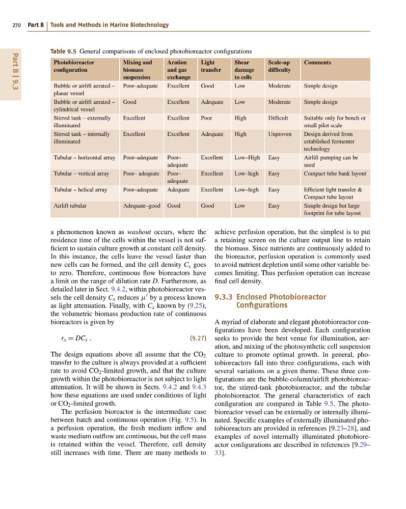
Table 9.5 General comparisons of enclosed photobioreactor configurations
Photobioreactor
configuration
Mixing and
biomass
suspension
Aration
and gas
exchange
Light
transfer
Shear
damage
to cells
Scale-up
difficulty
Comments
Bubble or airlift aerated –
planar vessel
Poor–adequate
Excellent
Good
Low
Moderate
Simple design
Bubble or airlift aerated –
cylindrical vessel
Good
Excellent
Adequate
Low
Moderate
Simple design
Stirred tank – externally
illuminated
Excellent
Excellent
Poor
High
Difficult
Suitable only for bench or
small pilot scale
Stirred tank – internally
illuminated
Excellent
Excellent
Adequate
High
Unproven
Design derived from
established fermenter
technology
Tubular – horizontal array Poor–adequate
Poor–
adequate
Excellent
Low–High Easy
Airlift pumping can be
used
Tubular – vertical array
Poor– adequate Poor–
adequate
Excellent
Low–high
Easy
Compact tube bank layout
Tubular – helical array
Poor–adequate
Adequate
Excellent
Low–high
Easy
Efficient light transfer &
Compact tube layout
Airlift tubular
Adequate–good Good
Good
Low
Easy
Simple design but large
footprint for tube layout
a phenomenon known as washout occurs, where the
residence time of the cells within the vessel is not sufficient to sustain culture growth at constant cell density.
In this instance, the cells leave the vessel faster than
new cells can be formed, and the cell density C x goes
to zero. Therefore, continuous flow bioreactors have
a limit on the range of dilution rate D. Furthermore, as
detailed later in Sect. 9.4.2, within photobioreactor vessels the cell density C x reduces
0 by a process known
as light attenuation. Finally, with C x known by (9.25),
the volumetric biomass production rate of continuous
bioreactors is given by
r x D DC x :
(9.27)
The design equations above all assume that the CO 2
transfer to the culture is always provided at a sufficient
rate to avoid CO 2 -limited growth, and that the culture
growth within the photobioreactor is not subject to light
attenuation. It will be shown in Sects. 9.4.2 and 9.4.3
how these equations are used under conditions of light
or CO 2 -limited growth.
The perfusion bioreactor is the intermediate case
between batch and continuous operation (Fig. 9.5). In
a perfusion operation, the fresh medium inflow and
waste medium outflow are continuous, but the cell mass
is retained within the vessel. Therefore, cell density
still increases with time. There are many methods to
achieve perfusion operation, but the simplest is to put
a retaining screen on the culture output line to retain
the biomass. Since nutrients are continuously added to
the bioreactor, perfusion operation is commonly used
to avoid nutrient depletion until some other variable becomes limiting. Thus perfusion operation can increase
final cell density.
9.3.3 Enclosed Photobioreactor
Configurations
A myriad of elaborate and elegant photobioreactor configurations have been developed. Each configuration
seeks to provide the best venue for illumination, aeration, and mixing of the photosynthetic cell suspension
culture to promote optimal growth. In general, photobioreactors fall into three configurations, each with
several variations on a given theme. These three configurations are the bubble-column/airlift photobioreactor, the stirred-tank photobioreactor, and the tubular
photobioreactor. The general characteristics of each
configuration are compared in Table 9.5. The photobioreactor vessel can be externally or internally illuminated. Specific examples of externally illuminated photobioreactors are provided in references [9.23–28], and
examples of novel internally illuminated photobioreactor configurations are described in references [9.29–
33].
270 Part B Tools and Methods in Marine Biotechnology
Table 9.5 General comparisons of enclosed photobioreactor configurations
Photobioreactor
configuration
Mixing and
biomass
suspension
Aration
and gas
exchange
Light
transfer
Shear
damage
to cells
Scale-up
difficulty
Comments
Bubble or airlift aerated –
planar vessel
Poor–adequate
Excellent
Good
Low
Moderate
Simple design
Bubble or airlift aerated –
cylindrical vessel
Good
Excellent
Adequate
Low
Moderate
Simple design
Stirred tank – externally
illuminated
Excellent
Excellent
Poor
High
Difficult
Suitable only for bench or
small pilot scale
Stirred tank – internally
illuminated
Excellent
Excellent
Adequate
High
Unproven
Design derived from
established fermenter
technology
Tubular – horizontal array Poor–adequate
Poor–
adequate
Excellent
Low–High Easy
Airlift pumping can be
used
Tubular – vertical array
Poor– adequate Poor–
adequate
Excellent
Low–high
Easy
Compact tube bank layout
Tubular – helical array
Poor–adequate
Adequate
Excellent
Low–high
Easy
Efficient light transfer &
Compact tube layout
Airlift tubular
Adequate–good Good
Good
Low
Easy
Simple design but large
footprint for tube layout
a phenomenon known as washout occurs, where the
residence time of the cells within the vessel is not sufficient to sustain culture growth at constant cell density.
In this instance, the cells leave the vessel faster than
new cells can be formed, and the cell density C x goes
to zero. Therefore, continuous flow bioreactors have
a limit on the range of dilution rate D. Furthermore, as
detailed later in Sect. 9.4.2, within photobioreactor vessels the cell density C x reduces
0 by a process known
as light attenuation. Finally, with C x known by (9.25),
the volumetric biomass production rate of continuous
bioreactors is given by
r x D DC x :
(9.27)
The design equations above all assume that the CO 2
transfer to the culture is always provided at a sufficient
rate to avoid CO 2 -limited growth, and that the culture
growth within the photobioreactor is not subject to light
attenuation. It will be shown in Sects. 9.4.2 and 9.4.3
how these equations are used under conditions of light
or CO 2 -limited growth.
The perfusion bioreactor is the intermediate case
between batch and continuous operation (Fig. 9.5). In
a perfusion operation, the fresh medium inflow and
waste medium outflow are continuous, but the cell mass
is retained within the vessel. Therefore, cell density
still increases with time. There are many methods to
achieve perfusion operation, but the simplest is to put
a retaining screen on the culture output line to retain
the biomass. Since nutrients are continuously added to
the bioreactor, perfusion operation is commonly used
to avoid nutrient depletion until some other variable becomes limiting. Thus perfusion operation can increase
final cell density.
9.3.3 Enclosed Photobioreactor
Configurations
A myriad of elaborate and elegant photobioreactor configurations have been developed. Each configuration
seeks to provide the best venue for illumination, aeration, and mixing of the photosynthetic cell suspension
culture to promote optimal growth. In general, photobioreactors fall into three configurations, each with
several variations on a given theme. These three configurations are the bubble-column/airlift photobioreactor, the stirred-tank photobioreactor, and the tubular
photobioreactor. The general characteristics of each
configuration are compared in Table 9.5. The photobioreactor vessel can be externally or internally illuminated. Specific examples of externally illuminated photobioreactors are provided in references [9.23–28], and
examples of novel internally illuminated photobioreactor configurations are described in references [9.29–
33].