

15 The Europipe Landfall Project
163
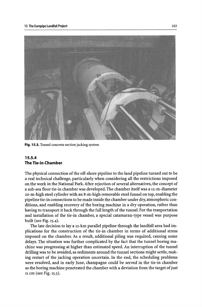
Fig. 15.3. Tunnel concrete section jacking system
15.5.4
The Tie-in Chamber
The physical connection of the off-shore pipeline to the land pipeline turned out to be
a real technical challenge, particularly when considering all the restrictions imposed
on the work in the National Park. After rejection of several alternatives, the concept of
a sub-sea floor tie-in chamber was developed. The chamber itself was a 12-m-diameter
20-m-high steel cylinder with an 8-m-high removable steel funnel on top, enabling the
pipeline tie-in connections to be made inside the chamber under dry, atmospheric conditions, and enabling recovery of the boring machine in a dry operation, rather than
having to transport it back through the full length of the tunnel. For the tranportation
and installation of the tie-in chamber, a special catamaran-type vessel was purpose
built (see Fig. 15.4).
The late decision to lay a 12-km parallel pipeline through the landfall area had implications for the construction of the tie-in chamber in terms of additional stress
imposed on the chamber. As a result, additional piling was required, causing some
delays. The situation was further complicated by the fact that the tunnel boring machine was progressing at higher than estimated speed. An interruption of the tunnel
drilling was to be avoided, as sediments around the tunnel sections might settle, making restart of the jacking operation uncertain. In the end, the scheduling problems
were resolved, and in early June, champagne could be served in the tie-in chamber
as the boring machine penetrated the chamber with a deviation from the target of just
11 cm (see Fig. 15.5).
163
Fig. 15.3. Tunnel concrete section jacking system
15.5.4
The Tie-in Chamber
The physical connection of the off-shore pipeline to the land pipeline turned out to be
a real technical challenge, particularly when considering all the restrictions imposed
on the work in the National Park. After rejection of several alternatives, the concept of
a sub-sea floor tie-in chamber was developed. The chamber itself was a 12-m-diameter
20-m-high steel cylinder with an 8-m-high removable steel funnel on top, enabling the
pipeline tie-in connections to be made inside the chamber under dry, atmospheric conditions, and enabling recovery of the boring machine in a dry operation, rather than
having to transport it back through the full length of the tunnel. For the tranportation
and installation of the tie-in chamber, a special catamaran-type vessel was purpose
built (see Fig. 15.4).
The late decision to lay a 12-km parallel pipeline through the landfall area had implications for the construction of the tie-in chamber in terms of additional stress
imposed on the chamber. As a result, additional piling was required, causing some
delays. The situation was further complicated by the fact that the tunnel boring machine was progressing at higher than estimated speed. An interruption of the tunnel
drilling was to be avoided, as sediments around the tunnel sections might settle, making restart of the jacking operation uncertain. In the end, the scheduling problems
were resolved, and in early June, champagne could be served in the tie-in chamber
as the boring machine penetrated the chamber with a deviation from the target of just
11 cm (see Fig. 15.5).