

512
BRUCE HACKETT ET AL.
of the superstructure. It may be formulated in the well-known form
F wind =
1
2
ρ a (A h + A s )C d U w U w ,
(3)
where ρ a is the density of air, A s is the superstructure area, A h is the
wind-exposed hull area, C d is a drag coefficient and U w is the wind
velocity. f form in eq. 2 is the form drag or damping force exerted by the
water on the hull due to the relative motion; it depends on the wet lateral
area of the hull, i.e., the length and draft. F wave is the wave drift force
acting on the hull, while f wave is the wave damping a counterforce that
occurs as the moving hull generates its own wave field. Much research
has been done to determine the wave drift and damping. Numerical
simulations of individual tanker hulls and idealized objects at DnV have
shown that representing hulls with a simple rectangular box of similar
dimensions is a fair approximation. Thus, a ship may be parameterized
using just the length, beam and draft. The wave forces on a given hull
are calculated as functions of the wave spectrum. DnV have tabulated
transfer functions in wave frequency space for both the wave drift and
wave damping forces, for a range of box hull dimensions. The forces for a
particular ship may then be estimated by interpolation in the database.
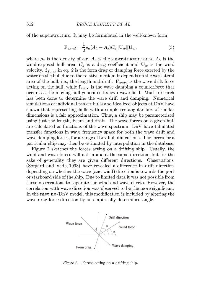
Figure 2 sketches the forces acting on a drifting ship. Usually, the
wind and wave forces will act in about the same direction, but for the
Observations
(
depending on whether the wave (and wind) direction is towards the port
or starboard side of the ship. Due to limited data it was not possible from
those observations to separate the wind and wave effects. However, the
correlation with wave direction was observed to be the more significant.
In the met.no/DnV model, this modification is included by altering the
wave drag force direction by an empirically determined angle.
Figure 2. Forces acting on a drifting ship.
sake of generality they are given different directions.
Sørg˚ ard and Vada, 1998) have revealed a difference in drift direction
BRUCE HACKETT ET AL.
of the superstructure. It may be formulated in the well-known form
F wind =
1
2
ρ a (A h + A s )C d U w U w ,
(3)
where ρ a is the density of air, A s is the superstructure area, A h is the
wind-exposed hull area, C d is a drag coefficient and U w is the wind
velocity. f form in eq. 2 is the form drag or damping force exerted by the
water on the hull due to the relative motion; it depends on the wet lateral
area of the hull, i.e., the length and draft. F wave is the wave drift force
acting on the hull, while f wave is the wave damping a counterforce that
occurs as the moving hull generates its own wave field. Much research
has been done to determine the wave drift and damping. Numerical
simulations of individual tanker hulls and idealized objects at DnV have
shown that representing hulls with a simple rectangular box of similar
dimensions is a fair approximation. Thus, a ship may be parameterized
using just the length, beam and draft. The wave forces on a given hull
are calculated as functions of the wave spectrum. DnV have tabulated
transfer functions in wave frequency space for both the wave drift and
wave damping forces, for a range of box hull dimensions. The forces for a
particular ship may then be estimated by interpolation in the database.
Figure 2 sketches the forces acting on a drifting ship. Usually, the
wind and wave forces will act in about the same direction, but for the
Observations
(
depending on whether the wave (and wind) direction is towards the port
or starboard side of the ship. Due to limited data it was not possible from
those observations to separate the wind and wave effects. However, the
correlation with wave direction was observed to be the more significant.
In the met.no/DnV model, this modification is included by altering the
wave drag force direction by an empirically determined angle.
Figure 2. Forces acting on a drifting ship.
sake of generality they are given different directions.
Sørg˚ ard and Vada, 1998) have revealed a difference in drift direction