

18 Field Radiometry and Ocean Color Remote Sensing
311
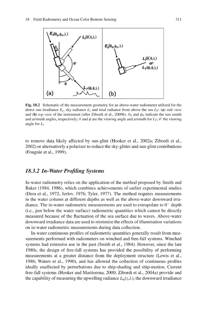
Fig. 18.2 Schematic of the measurement geometry for an above-water radiometer utilized for the
direct sun irradiance E s , sky radiance L i and total radiance from above the sea L T : (a) side view
and (b) top view of the instrument (after Zibordi et al., 2009b). θ 0 and φ 0 indicate the sun zenith
and azimuth angles, respectively; θ and φ are the viewing angle and azimuth for L T ; θ the viewing
angle for L i
to remove data likely affected by sun-glint (Hooker et al., 2002a; Zibordi et al.,
2002) or alternatively a polarizer to reduce the sky-glitter and sun-glint contributions
(Fougnie et al., 1999).
18.3.2 In-Water Profiling Systems
In-water radiometry relies on the application of the method proposed by Smith and
Baker (1984, 1986), which combines achievements of earlier experimental studies
(Dera et al., 1972; Jerlov, 1976; Tyler, 1977). The method requires measurements
in the water column at different depths as well as the above-water downward irradiance. The in-water radiometric measurements are used to extrapolate to 0 − depth
(i.e., just below the water surface) radiometric quantities which cannot be directly
measured because of the fluctuation of the sea surface due to waves. Above-water
downward irradiance data are used to minimize the effects of illumination variations
on in-water radiometric measurements during data collection.
In-water continuous profiles of radiometric quantities generally result from measurements performed with radiometers on winched and free-fall systems. Winched
systems had extensive use in the past (Smith et al., 1984). However, since the late
1980s, the design of free-fall systems has provided the possibility of performing
measurements at a greater distance from the deployment structure (Lewis et al.,
1986; Waters et al., 1990), and has allowed the collection of continuous profiles
ideally unaffected by perturbations due to ship-shading and ship-motion. Current
free-fall systems (Hooker and Maritorena, 2000; Zibordi et al., 2004a) provide and
the capability of measuring the upwelling radiance L u (z,λ), the downward irradiance
311
Fig. 18.2 Schematic of the measurement geometry for an above-water radiometer utilized for the
direct sun irradiance E s , sky radiance L i and total radiance from above the sea L T : (a) side view
and (b) top view of the instrument (after Zibordi et al., 2009b). θ 0 and φ 0 indicate the sun zenith
and azimuth angles, respectively; θ and φ are the viewing angle and azimuth for L T ; θ the viewing
angle for L i
to remove data likely affected by sun-glint (Hooker et al., 2002a; Zibordi et al.,
2002) or alternatively a polarizer to reduce the sky-glitter and sun-glint contributions
(Fougnie et al., 1999).
18.3.2 In-Water Profiling Systems
In-water radiometry relies on the application of the method proposed by Smith and
Baker (1984, 1986), which combines achievements of earlier experimental studies
(Dera et al., 1972; Jerlov, 1976; Tyler, 1977). The method requires measurements
in the water column at different depths as well as the above-water downward irradiance. The in-water radiometric measurements are used to extrapolate to 0 − depth
(i.e., just below the water surface) radiometric quantities which cannot be directly
measured because of the fluctuation of the sea surface due to waves. Above-water
downward irradiance data are used to minimize the effects of illumination variations
on in-water radiometric measurements during data collection.
In-water continuous profiles of radiometric quantities generally result from measurements performed with radiometers on winched and free-fall systems. Winched
systems had extensive use in the past (Smith et al., 1984). However, since the late
1980s, the design of free-fall systems has provided the possibility of performing
measurements at a greater distance from the deployment structure (Lewis et al.,
1986; Waters et al., 1990), and has allowed the collection of continuous profiles
ideally unaffected by perturbations due to ship-shading and ship-motion. Current
free-fall systems (Hooker and Maritorena, 2000; Zibordi et al., 2004a) provide and
the capability of measuring the upwelling radiance L u (z,λ), the downward irradiance